


SKY497
Installation Manual
vi
Rev. C
LIST OF ILLUSTRATIONS
Figure
Page
1-1
Surveillance Zone .............................................................................................................1-2
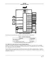
1-2
Main Components ............................................................................................................1-3
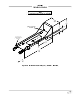
1-3
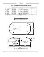
Standard TRC Mounting Tray (P/N 805-10870-001) .....................................................1-5
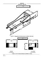
1-4
Ruggedized TRC Mounting Tray (P/N 805-10870-003)..................................................1-6
1-5
P1 Connector Dimensions (Reference Only)...................................................................1-6
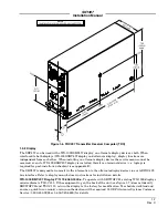
1-6
TRC Transmitter Receiver Computer (TRC)..................................................................1-7
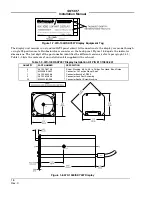
1-7
WX-1000/SKY497 Display Equipment Tag ....................................................................1-8
1-8
WX-1000/SKY497 Display ...............................................................................................1-8
1-9
NY164 Directional Antenna ..........................................................................................1-10
2-1
Directional Antenna Mounting Location ........................................................................2-2
2-2
Interconnect Wiring Without WX-1000 ..........................................................................2-3
2-3
Interconnect Wiring With WX-1000................................................................................2-7
2-4
Connector P1 Contact Arrangement .............................................................................2-14
2-5
Display Cable..................................................................................................................2-17
2-6
KCS55 Heading Flag Connection..................................................................................2-18
2-7
Heading Input Cable ......................................................................................................2-19
2-8
Antenna Mounting Holes...............................................................................................2-24
2-9
Directional Antenna Installation ..................................................................................2-24
2-10
Mounting Holes for Standard Mount Tray, P/N 805-10870-001 .................................2-25
2-11
Mounting Holes for Ruggedized Mount Tray, P/N 805-10870-003 .............................2-25
2-12
TRC Installation .............................................................................................................2-27
2-13
Instrument Panel Cutout and Mounting Holes............................................................2-28
2-14
Display Installation........................................................................................................2-29
3-1
Controls.............................................................................................................................3-1
3-2
Start-up Screen.................................................................................................................3-2
3-3
Standby Screen.................................................................................................................3-3
3-4
Typical Patch Antenna Tripod Mount.............................................................................3-5
3-5
Self Test Screen ................................................................................................................3-6
3-6
Self Test Failed Screen ....................................................................................................3-7
4-1
Service Menu ....................................................................................................................4-2
4-2
Calibration Screen............................................................................................................4-3
4-3
Successful Re-Calibration ................................................................................................4-3
4-4
Failed Calibration ............................................................................................................4-4
4-5
System Log........................................................................................................................4-4
4-6
System Data......................................................................................................................4-5
4-7
Software Version ..............................................................................................................4-6
4-8
Configuration - Page 1 .....................................................................................................4-7
4-9
Configuration - Page 2 .....................................................................................................4-8
4-10
Configuration - Page 3 .....................................................................................................4-8
4-11
Configuration - Page 4 .....................................................................................................4-9
4-12
Data Monitor - Page 1 ....................................................................................................4-10
4-13
Data Monitor - Page 2 ....................................................................................................4-10
4-14
Data Monitor - Page 3 ....................................................................................................4-11
4-15
Data Monitor - Page 4 ....................................................................................................4-12
4-16
Data Monitor - Page 5 ....................................................................................................4-12
4-17
Ground Test ....................................................................................................................4-13
4-18
Adapter Plug Jumper Installation ................................................................................4-18
4-19
Adapter Plug Assembly..................................................................................................4-18


