


Page 4
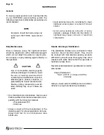
The lighthead Data Labels contain the lighthead
model number, bulb type, fuse type, electrical specifications
and product serial number.
LIGHTHEAD LABEL
WALL CONTROL LABEL
CAT. NO.
INPUT
LED SOURCE
CAT. NO.
INPUT
OUTPUT
SAFETY FUSE
AUR5
AUR7
30VDC
30VDC
3.8A
4.8A
114W
144W
B1-710-00
B1-710-01
Single
Dual
Triple
B9-710-01
B9-710-02
B9-710-03
100V~240V
100V~240V
100V~240V
144W
288W
432W
50/60Hz
50/60Hz
50/60Hz
30V DC
30V DC
30V DC
4.8A
9.6A
14.4A
144W
288W
432W
2A
2A x 2
2A x 3
TIMELAG
TIMELAG
TIMELAG
Manufactured for SKYTRON by DAI-ICHI SHOMEI CO., LTD. TOKYO, JAPAN
GRAND RAPIDS, MI · 616.656.2900
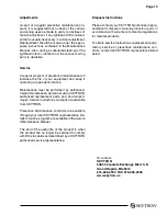
INPUT
100V~240V AC
CAT. NO.
ELECTRICAL RATING
OUTPUT
30V DC
SERIAL NO.
0000
SAFETY FUSE
TIMELAG
Manufactured for SKYTRON by DAI-ICHI SHOMEI CO., LTD. TOKYO, JAPAN
GRAND RAPIDS, MI · 616.656.2900
INPUT
CAT. NO.
LIGHTHEAD
ELECTRICAL RATING
LED SOURCE
SERIAL NO.
0000
30V DC
PORTABLE STAND LIGHT LABEL
Manufactured for SKYTRON by DAI-ICHI SHOMEI CO., LTD. TOKYO, JAPAN
GRAND RAPIDS, MI · 616.656.2900
INPUT
CAT. NO.
ELECTRICAL RATING
OUTPUT
SERIAL NO.
0001
SAFETY FUSE
2A x2 TIMELAG
30V DC
3.8A 114W
100V~240V AC
111W
50/60Hz
AUR 5S
EQUIPMENT LABELS AND SPECIFICATIONS (continued)
Содержание AURORA LED 5 4000K
Страница 1: ...REV 9 08 INSTALLATION INSTRUCTIONS LED SERIES SURGICAL LIGHTS...
Страница 18: ...Page 16...
Страница 20: ...Page 18...
Страница 26: ...5085 Corporate Exchange Blvd S E Grand Rapids MI 49512 1 616 656 2900 FAX 1 616 656 2906...
Страница 27: ...LED SERIES SURGICAL LIGHTS OPERATORS MANUAL TEC B 0002 REV0 1 09...
Страница 47: ...5085 Corporate Exchange Blvd S E Grand Rapids MI 49512 616 656 2900 FAX 616 656 2906...
Страница 48: ...PARTS CATALOG LED SERIES SURGICAL LIGHT TEC B 0009 REV3 3 10...
Страница 54: ...Page 5 17 Stand Model Support Post Assembly page 40...
Страница 65: ...Page 16 6 LED POD ASSEMBLY 57 010307 03mj 3 2 1 4 10 5 6 7 12 13 15 14 15 13 16 8 11 9...
Страница 73: ...Page 24 10 LIGHTHEAD ASSEMBLY 1 2 6 7 8 9 11 13 14 12 10 5 3 4 57 031408 06mj...
Страница 81: ...Page 32 13 TV LIGHTHEAD ASSEMBLY 1 3 4 5 6 7 8 9 10 11 12 15 17 18 13 16 14 2 5tv 081308 03...
Страница 83: ...Page 34 14 WALL CONTROL ASSEMBLY 57 010307 04 1 5 6 9 10 3 2 7 8 4...
Страница 85: ...Page 36 15 WALL CONTROL COMPONENTS 57 010307 05 1 2 3 4 5 6 12 13 14 7 8 9 10 11...
Страница 91: ...5085 Corporate Exchange Blvd S E Grand Rapids MI 49512 616 656 2900 FAX 616 656 2906...
Страница 92: ...MAINTENANCE MANUAL LED SERIES SURGICAL LIGHT 7 07...
Страница 93: ......
Страница 95: ...Page 2...
Страница 110: ...5085 Corporate Exchange Blvd S E Grand Rapids MI 49512 616 656 2900 FAX 616 656 2906...
Страница 111: ...REV 8 08 INSTALLATION INSTRUCTIONS LFS SERIES SURGICAL LIGHTS...
Страница 133: ...Page 21...
Страница 135: ...Page 23...
Страница 138: ...5085 Corporate Exchange Blvd S E Grand Rapids MI 49512 1 616 656 2900 FAX 1 616 656 2906...
Страница 139: ...LFS SERIES OWNERS MANUAL REV 6 08...
Страница 140: ......
Страница 142: ...Page 2...
Страница 160: ...Page 20...
Страница 170: ...5085 Corporate Exchange Blvd S E Grand Rapids MI 49512 1 616 656 2900 FAX 1 616 656 2906...
Страница 171: ...INSTALLATION INSTRUCTIONS AUR SERIES SURGICAL LIGHTS TEC B 0006 REV1 8 09...
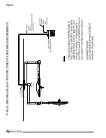
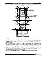
Страница 188: ...Page 16 TYPICAL AURORA AUR LIGHT FIXTURE CONDUIT AND WIRING REQUIREMENTS...
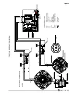
Страница 189: ...Page 17 TYPICAL WIRING DIAGRAM...
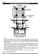
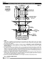
Страница 190: ...Page 18 TYPICAL AURORA AURTV LIGHT FIXTURE CONDUIT AND WIRING REQUIREMENTS...
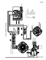
Страница 191: ...Page 19 TYPICAL WIRING DIAGRAM...
Страница 196: ...5085 Corporate Exchange Blvd S E Grand Rapids MI 49512 1 616 656 2900 FAX 1 616 656 2906...
Страница 197: ...AUR SERIES SURGICAL LIGHTS OPERATORS MANUAL TEC B 0003 REV9 3 10...
Страница 198: ......
Страница 219: ......
Страница 220: ...5085 Corporate Exchange Blvd S E Grand Rapids MI 49512 616 656 2900 FAX 616 656 2906...
Страница 221: ...PARTS CATALOG AUR SERIES SURGICAL LIGHT TEC B 0004 REV6 6 10...
Страница 222: ......
Страница 229: ...Page 7 21 AUR Stand Model Base Assembly page 48 22 AUR Stand Model Support Post Assembly page 50...
Страница 232: ...Page 10 2 AUR5 7 LED POD ASSEMBLY LED POD ASSEMBLY 013009 19mj 1 3 2 4 18 5 6 9 10 7 8 17 13 16 15 11 17 14 12 17 15 13...
Страница 264: ...Page 42 18 LIGHTHEAD ASSEMBLY AUR5TV AUR 5TV LIGHTHEAD ASSEMBLY 013009 07mj 1 2 3 4 5 6 7 13 12 11 10 15 14 16 17 18 9 8...
Страница 266: ...Page 44 19 LIGHTHEAD ASSEMBLY AUR7TV AUR 7TV LIGHTHEAD ASSEMBLY 013009 09mj 1 6 2 5 3 4 7 13 12 11 10 15 14 16 17 18 9 8...
Страница 274: ...5085 Corporate Exchange Blvd S E Grand Rapids MI 49512 616 656 2900 FAX 616 656 2906...
Страница 275: ...AUR SERIES SURGICAL LIGHTS MAINTENANCE MANUAL TEC B 0007 REV1 1 10...
Страница 276: ......
Страница 278: ...Page 2...
Страница 292: ...Page 16 TYPICAL WIRING DIAGRAM...
Страница 293: ......
Страница 294: ...5085 Corporate Exchange Blvd S E Grand Rapids MI 49512 616 656 2900 FAX 616 656 2906...
Страница 295: ...TEC B 0008 REV3 3 10 OWNERS MANUAL HANDLE CAMERA SYSTEM...
Страница 296: ......
Страница 308: ...Page 12 PRECISION HD CAMERA SYSTEM...
Страница 310: ...5085 Corporate Exchange Blvd S E Grand Rapids MI 49512 1 616 656 2900 FAX 1 616 656 2906...


