深圳市天工测控技术有限公司
SKW71-User Manual
SKW71-UM-001,A/1
3
1
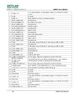
VDD_3.3V
3.3V input 1000mA, recommended voltage 3.3V,Min2.97V, MAX
3.63V
2
GND
Ground
3
GPIO_23
KEY_INPUT, be free for customer defined.
4
WAN_
Ethernet port
5
I2S_WS(GPIO_19)
Word select for stereo
6
WAN_PORT_RX-
Ethernet port
7
I2S_MICIN(GPIO_22)
I2S Data input
8
WAN_
Ethernet port
9
I2S_MCK(GPIO_21)
Master clock
10 WAN_PORT_TX-
Ethernet port
11 I2S_SD(GPIO_20)
Serial data input/output
12 LAN_P
Ethernet port
13 I2S_CK(GPIO_18)
Stereo clock
14 LAN_PORT0_RX-
Ethernet port
15 USB +
USB signal, carries USB data to and from the USB 2.0 PHY
16 LAN_P
Ethernet port
17 USB -
USB signal, carries USB data to and from the USB 2.0 PHY
18 LAN_PORT0_TX-
Ethernet port
19 LED7(GPIO_27)
SYSTEM LED
20 GND
Ground
21 LED8(GPIO_26)
JMP_START LED
22 VDD_2.0V OUTPUT
Power supply output for peripheral network transformer
23
RESET_CONFIG
(UART_CTS)
(GPIO_12)
resets the firmware to its default configuration, it has a internal
10k drop down resistance, and trigger while Pulling up
24 VDD_2.0V OUTPUT
Power supply output for peripheral network transformer
25
JUMPSTART
(UART_RTS) (GPIO_11)
KEY_INPUT to start WPS function, it has a internal 10k drop
down resistance, and trigger while Pulling up
26 GND
Ground
27 GND
Ground
28 SPI_MISO
SPI serial interface
29 VDD_3.3V
3.3V input 1000mA, recommended voltage 3.3V,Min2.97V, MAX
3.63V
30 SPI_CLK
SPI serial interface
31 VDD_3.3V
3.3V input 1000mA, recommended voltage 3.3V, Min2.97V, MAX
3.63V
32 SPI_MOSI
SPI serial interface
33 LED6 (GPIO_17)
WLAN LED


