background image

D

Please refer to Appendix 6 for instructions on how to mount the solar panel on a pole.

2.4 Pole Mount/Bracket for the D SKM 225A

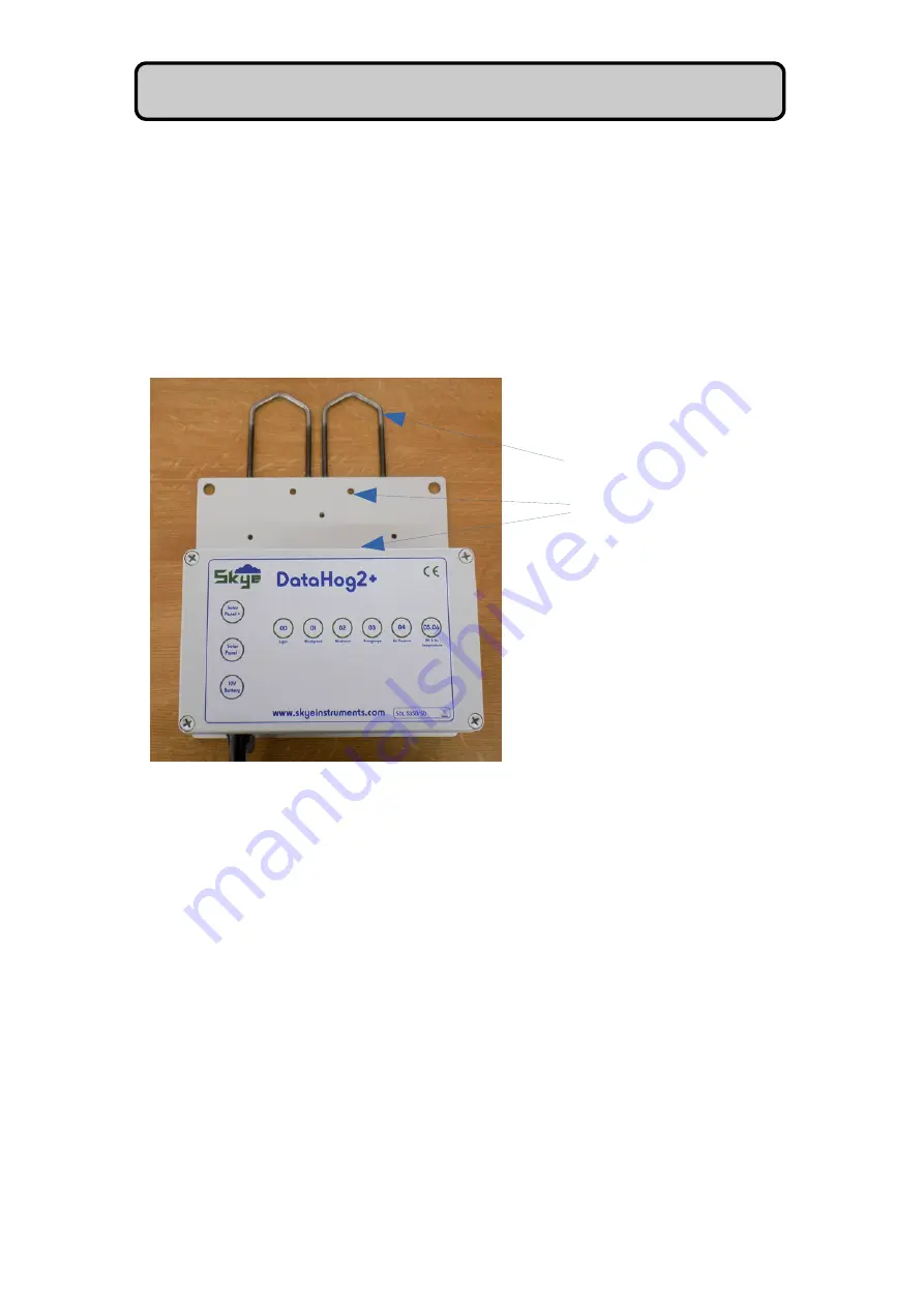
If a pole mount has been ordered at the same time as the D, then the enclosure 
will be pre-mounted on the bracket.  Connection holes, accessible by removing the lid of the 
enclosure, line up with holes in the mounting plate.  A pair of 'V' bolts plus nuts etc are 
supplied so that the unit can be fixed to a pole.

2.5 Activity LED Lights

There are 8 coloured LED lights which light up and flash in different sequences depending on
the intended function or activity.

When the power supply is first connected all the LEDs will continually flash in turn, until the 
DataHog has undergone its setup routine.  When this has happened the DataHog will settle 
into its normal operating routine as follows:

LED 1   - DataHog 'wake-up' string is detected
LED 2  - DataHog 'datastring' detected
LED 3  - Complete 'datastring' successfully received
LED 4  - 'Datastring' stored on the SDHC card successfully
LED 5 -  Indicates a search is being made for the 'datastring' but none was found
LED 6, 7 & 8 – SDHC card storage attempt failed.

10

'V' bolts for fixing bracket to a pole

 through these holes

Содержание DataHog2+

Страница 1: ...DataHog2 Skye Instruments Ltd 21 Ddole Enterprise Park Llandrindod Wells Powys LD1 6DF UK Tel 44 0 1597 824811 Email skyemail skyeinstruments com www skyeinstruments com Iss 1 0...

Страница 2: ...y of the methods below Click on the icons to browse to the sites or search for the usernames below Have a Smartphone Scan this QR code to access our website for more information about your product Ple...

Страница 3: ...3 Internal temperature channel 16 3 2 4 Digital input channels 16 3 2 5 Internal relative humidity channel 17 3 2 6 Software channels 17 3 2 7 Relay output channels 17 3 3 Calibration 17 3 4 Firmware...

Страница 4: ...meter Sensors 40 5 8 Special Socket RH Air Temperature Sensors 40 5 9 Relay Outputs _____________________________________________ 40 6 0 SkyeLynx Comms Software 41 7 0 Importing Data into Excel 42 8 0...

Страница 5: ...ur model and type of your unit and ignore inapplicable sections In normal logging mode the p will be woken up by the clock at regular 10 second intervals The p will keep track of real time by counting...

Страница 6: ...g2 will still store data in its internal memory at the same time but will also store data on the Multi Media SDHC card There is no need to offload the data from the internal memory storage as a copy w...

Страница 7: ...ug is removed and the plug from the datalead is inserted 4 DHLC3 electronics board 5 Row of Activity Function LEDs 6 SDHC card holder 7 Push button for activating the blue LED for SDHC card removable...

Страница 8: ...e To remove the card gently press down on the card and then let go This will release it from the locking mechanism 2 2 1 Removing Inserting the SDHC Card in Use The SDHC card is located inside the enc...

Страница 9: ...utomatically created at midnight Day files are a space delimited text file and easily read by any spreadsheet software Please refer to Appendix 7 for details of the SDHC card structure 2 3 Power Suppl...

Страница 10: ...ured LED lights which light up and flash in different sequences depending on the intended function or activity When the power supply is first connected all the LEDs will continually flash in turn unti...

Страница 11: ...then the above LED sequence will occur LEDS 6 7 8 continuously flash and LEDS 1 2 3 4 5 flash according to the datastrings generated by the DataHog This indicates either no SDHC card is present or the...

Страница 12: ...taHog2 does not have any internal batteries so please disregard any reference to internal batteries in the following pages Changing any of the configuration settings can be achieved by using the SkyeL...

Страница 13: ...a few locations required for housekeeping and the bulk of the storage capacity which is devoted to data storage The data is stored in a format that is constant Basically the data from each channel th...

Страница 14: ...h has been has been arranged so that each of its inputs may be used as a separate channel if required Usually only one or two of these channels will be fitted on any logger though the full list is sho...

Страница 15: ...feedback resistor It s precise value is given in the configuration certificate for each DataHog2 The ratio of current in to voltage out is given by the following Current in for F S voltage out 2 000 2...

Страница 16: ...12 thermistor channels are required If it is fitted it may be addressed as channel 45 and will give an output as per a standard thermistor channel Hardware Channel NumberFunction and Description 45 Th...

Страница 17: ...range NOTE each digital hardware channel should not have more than one software channel assigned to them as once they have been read by the first software channel the counter is returned to zero 3 2 7...

Страница 18: ...e is sent from the DataHog2 via RS232 requesting a response An audible beep generally precedes the second or so that the unit spends listening The DataHog2 will only spend this extra time with the RS2...

Страница 19: ...ve power the DataHog2 shuts down circuits not currently in use whenever possible In Logging Mode the operation is cyclic It is woken after approx 8 seconds by the internal clock it will collect and st...

Страница 20: ...is displayed as below and may be selected from by typing the menu option number or letter SKYE INSTRUMENTS LTD MINIMET SERIES SEND CHARACTER SHOWN TO SELECT ITEM ESC RETURNS TO LOGGING MAIN MENU 0 DIS...

Страница 21: ...metres per time interval of the space bar press in this mode NOTE always press Escape to leave Main Menu mode and return to Log Mode Else the logger will not record any data and batteries will drain...

Страница 22: ...y data and batteries will drain quickly 4 2 3 Option 2 Display Software Version This mode displays the version of the current logger software along with Skye contact details for help or service Please...

Страница 23: ...gger memory has become full and been overwriting the latest records in a continual loop you may find that the latest records will be in the middle of this data file not at the very beginning NOTE alwa...

Страница 24: ...MEMORY OVERWRITE 1 DISABLE MEMORY OVERWRITE 2 3 SET LOG START STOP TIME 4 5 EDIT DATAFILE IDENTIFIER 6 RETURN TO MAIN MENU Option 0 Enable memory Overwrite will enable the DataHog2 s memory to overwr...

Страница 25: ...ore than one system Your 12 characters will be repeated on screen for your confirmation before continuing The default Datafile Identifier setting entered at Skye includes the logger serial number e g...

Страница 26: ...hour 08 2 min 17 6 hour 09 5 min 18 12 hour Enter the code for the sampling time required A second similar submenu will then be displayed showing identical codes for choosing the storage time at which...

Страница 27: ...d link up to the PC Alternatively use Option E from the Main Menu Log on Demand mode see Section 3 2 15 Remember that RS232 communication drains the DataHog2 s internal batteries at a greater rate tha...

Страница 28: ...then be prompted to enter the sign of the offset or and a summary of your entries for that software channel will be displayed for you to accept reject or redo Acceptance or Escape will return to the...

Страница 29: ...a Voltage Inputs 0 23 Enter the hardware channel you wish to configure 0 23 and you will then be asked to specify the gain to use as below ENTER GAIN TO USE SELECT THE VOLTAGE GAIN 0 GAIN 1 2 0V F S 1...

Страница 30: ...our chosen scalecode usually Option 1 Ax B for voltage channels and the software will then display all the choices you have made for this voltage channel If correct press Y to accept and return to Mai...

Страница 31: ...ISTOR 10K 3 INTERNAL RH 4 WINDVANE 5 CHANNEL OFF Enter your chosen scalecode usually Option 1 Ax B for current channels and the software will display all the choices you have made for this current cha...

Страница 32: ...turn to Main Menu If at any time you wish to switch off this software channel e g to increase logging capacity choose Option 5 Channel Off from the Scalecode menu NOTE always press Escape to leave Mai...

Страница 33: ...mode and return to Log Mode Else the logger will not record any data and batteries will drain quickly 4 2 11e Internal Humidity Channel 54 Not relevant to the DataHog2 ENTER THE SCALE CODE TO USE SELE...

Страница 34: ...repeated on screen for your confirmation NOTE for humidity no sign or is needed only one decimal place is required format is xxx x e g 099 9 For thermistor channels the format is xxx xx plus a or sig...

Страница 35: ...y if it does not have a raw data value of zero This option is a memory saving procedure and prevents the memory being filled up with unnecessary zeros most applicable to digital channels Your choice o...

Страница 36: ...re required for relay and log thresholds on the same channel each must be individually entered NOTE always press Escape to leave Main Menu mode and return to Log Mode Else the logger will not record a...

Страница 37: ...w to dismantle and assemble the matching plugs are shown in Figure 2 Pin identification is shown in Figure 3 The sensor inputs are wired internally to the appropriate hardware channel as shown on the...

Страница 38: ...sors i Sockets for single channel light sensors Pin 1 not used Pin 2 not used Pin 3 not used Pin 4 signal output negative current channel input Pin 5 ground and cable screen ii Sockets for SKR 110 SKR...

Страница 39: ...connection of a differential voltage bridge type sensor e g an air pressure barometer soil moisture tensiometer water level sensor thermopile pyranometer etc N B Be sure that the DataHog2 s channel is...

Страница 40: ...s it is not a differential voltage input a For two 0 1V outputs e g SKH 2060 or 2065 Pin 1 positive excitation 5 000 volts Pin 2 not used Pin 3 0 1V RH input Pin 4 0 1V Temperature input Pin 5 ground...

Страница 41: ...SKYELYNX COMMS SOFTWARE The DataHog2 logger is supplied with SkyeLynx Comms software for easy communication to set up operate and download data from memory Please refer to the separate manual for ins...

Страница 42: ...the data as follows 1 Open Excel Click File Open and choose the file offloaded from your DataHog2 logger 2 Go through the Text Import Wizard steps 1 to 3 as shown below The data is now in columns in...

Страница 43: ...en mains supply and logger The ACC 9 Mains Hog consists of a voltage transformer which runs off mains power please specify 110V or 220V and provides a 12V supply to the logger The Mains Hog itself is...

Страница 44: ...ct like an aerial for picking up electrical noise Ensure that the cable length does not run alongside other electrical installations such as large switching machinery etc to eliminate data transfer pr...

Страница 45: ...data Pin 3 Ground cable screen link to Pin 6 Pin 4 not used Pin 5 not used Pin 6 Link to Pin 3 Pin 7 not used Pin 8 not used 9 PIN D CONNECTOR Pin 1 Link to Pin 4 6 Pin 2 Receive data Pin 3 transmit...

Страница 46: ...og2 FIG 2 SUB MINIATURE PLUGS 46 Nut Plastic Grip Rubber Sleeve Plug O Ring DO NOT USE PLUG IF O RING IS MISSING Metal Sleeve A A TO REMOVE METAL SLEEVE PRESS IN POINTS MARKED A ON DIAGRAM AT THE SAME...

Страница 47: ...DataHog2 FIG 3 DATAHOG SOCKETS PIN IDENTIFICATION 47 3 4 5 1 2 4 6 7 1 2 5 3 8 5 PIN SOCKETS Front outside view of socket 8 PIN SOCKETS Front outside view of socket...

Страница 48: ...0 2 0mV F S 2 DIGITAL INPUT CHANNELS a GAIN NOT APPLICABLE FOR DIGITAL CHANNELS b TERMINATION 00 for any digital channel 3 SCALECODE applicable to all channels 00 Raw data count 01 Ax B 02 Thermistor...

Страница 49: ...R VALUES NEED TO BE ENTERED AS 5 DIGITS PLUS A DECIMAL POINT LEADING ZEROS CANNOT BE USED 1 WINDSPEED SENSORS This example illustrates use with the Vector Instruments A100R anemometer which gives 1 pu...

Страница 50: ...his figure follow these steps Wake up the DataHog as usual to reveal the Main Menu Type 9 to set Ax B calibration factors Enter the Software Channel number for the raingauge channel Enter the Full Sca...

Страница 51: ...re channel numbers 1 23 The Full Scale Value is calculated by dividing the sensor output in units per mV by the chosen gain and multiplying the result by 2000 see example below REMEMBER VALUES NEED TO...

Страница 52: ...Pa From the sensor sensitivity 61 5 20 3 075 mV So an additional offset count of 3 075 mV must be taken into account Additional offset count 3 075 10 9 5 292 1 Hence new offset count 285 1 19 273 1 EN...

Страница 53: ...meter itself must have a minimum of 1k resistance A raw data count of 0 12 288 user scaled as wished can be set over the whole rotation of the potentiometer To enter a new full scale value choose Opti...

Страница 54: ...00 0 enter an Offset Count as 0000 and Connect the potentiometer to the DataHog2 input Set the potentiometer at one end of its travel Choose Option 0 from the DataHog2 Main Menu and press SPACEBAR to...

Страница 55: ...2 voltage readings measured in a above is the potentiometers zero offset Use this reading to calculate the DataHog2 MiniMet2 s Offset Count Calculate and enter as shown in Option 9 from the Main Menu...

Страница 56: ...l light up LEDs and show the voltage level of the battery When the battery is full the green LED labelled Batt Full will light up Close up of the Power Connector Take care when connecting the 12 volt...

Страница 57: ...the solar panel pole mount through the spacers which clamp the pole and then fit the nut 3 Repeat for the bottom holes of the solar panel pole mount 4 Tighten the nuts 5 The assembly should now be tig...

Страница 58: ...ustable spanner 10 The assembly should be angled to obtain maximum sunlight throughout the year before being fully tightened 11 The solar panel should now be covered temporarily the cardboard packing...

Страница 59: ...ataHog2 is powered ie switched off and then on It is an identifier to show the ID of the unit which is customisable and the time and date that the unit was started There will also be a Year folder Dou...

Отзывы: