Page 2 of 5
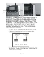
Edge “A”
Centered
Over Line
Buttons
Figure 1
CAUTION:
The SENSOR BOARD must be mounted and aligned correctly on the base
telephone, or the unit will not operate properly. If you need to remove the SENSOR
BOARD, slowly lift up on one edge of the SENSOR BOARD. Pulling the SENSOR
BOARD off too fast, will damage the foam pads. Excessive removal of the SENSOR
BOARD will weaken the adhesive on the SENSOR BOARD and will prevent it from
staying attached. If the SENSOR BOARD fails to stay attached to the phone, use a small
amount of Contact Cement, carefully applied with a Q-TIP, to re-attach the Sensor
Board. You MUST let the Contact Cement air cure for at least 20 seconds before
attaching to the phone. Please call for technical support for proper assistance in
cementing the SENSOR BOARD to the phone. DO NOT use any other type of glue,
cement, or tape on the SENSOR BOARD.
4-
The CK-1R black box can not be located under the base phone like other CK1
units.
5-
Connect the SENSOR BOARD CABLE between the CK1R Box and the
SENSOR BOARD as shown in Fig. 3.
6-
Disconnect the modular cable that is connected to the RCA Phone, at the “
L2/L1”
jack and hold it in your hand. Now connect the cord in your hand, to the
[1&2 To
Line]
jack on the CK-1R Black Box.
L4/Data
L4/L3
L2/L1
L2
Jacks on Rear of Phone
To Black Box
To Black Box
3&4 to Phone
1&2 to Phone
Edge “A”
On phone
Figure 2


