7
SKOPE Remote Glass Chiller – GC110r
Installation
SKOPE GC110r
Refrigeration Practice
Installation must be performed by a refrigeration tradesperson, to an appropriate
standard complying with all local regulations.
Performance depends on the overall installation (including condensing unit). Cabinet
suitability must always be quantified for the application. The final responsibility for
condensing unit performance and component selection rests with the installer. The
installer must check matters such as:
• Heat and refrigeration load
• Variable operating conditions (usage, ambient and humidity)
• Refrigeration pipe sizing and length (distance, elevation and pressure drop)
• Location and ventilation (cabinet and condensing unit)
• Drainage and power supply
• Evacuating the unit fully prior to charging
Drain
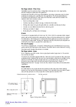
The cabinet is supplied with a 45 mm long, 3/4” (19 mm) O.D. evaporator drain spigot,
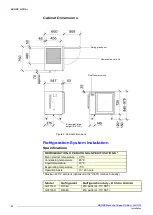
which exits out the bottom of the cabinet (see “Figure 2: Cabinet dimensions” on page 6
for dimensions). All drainage is to comply with local regulations, covering removal of
condensate to waste water. Ensure the cabinet is level and the drain has adequate fall.
Venting the drain may be required for a restrictive run.
Power Supply
The chiller is supplied with a 3.0 metre 10A flexible power cord fitted with a 3-pin plug,
which exits the left hand side of the cabinet. The chiller can be turned off and on using
the power switch beside the electronic controller.
Refrigeration lines
A 1/4” liquid line and 3/8” suction line are provided to attach pipe lines to. The suction
line must be insulated.
The electronic controller supplied with the cabinet can switch a solenoid. No solenoid is
supplied with the standard remote unit. If a solenoid valve is fitted and controlled by the
electronic controller, the solenoid will need to be connected to the connector block
behind the cover attached to the left hand side of the cabinet (see “Figure 3:
Refrigeration Services” on page 7). Ensure the solenoid connection is accessible after
installation.
Operation
On initial start up, the evaporator fan and cabinet heater wire will not immediately
operate, as they are thermostatically controlled. The evaporator fan and cabinet heater
wire will only operate once the evaporator coil temperature reaches 10°C.
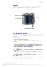
Figure 3: Refrigeration Services
Optional solenoid valve connection cover
3/8” suction line and
1/4” liquid line outlets
Mains supply power cord
Evaporator drain spigot
(3/4” O.D.)
On/off power switch


