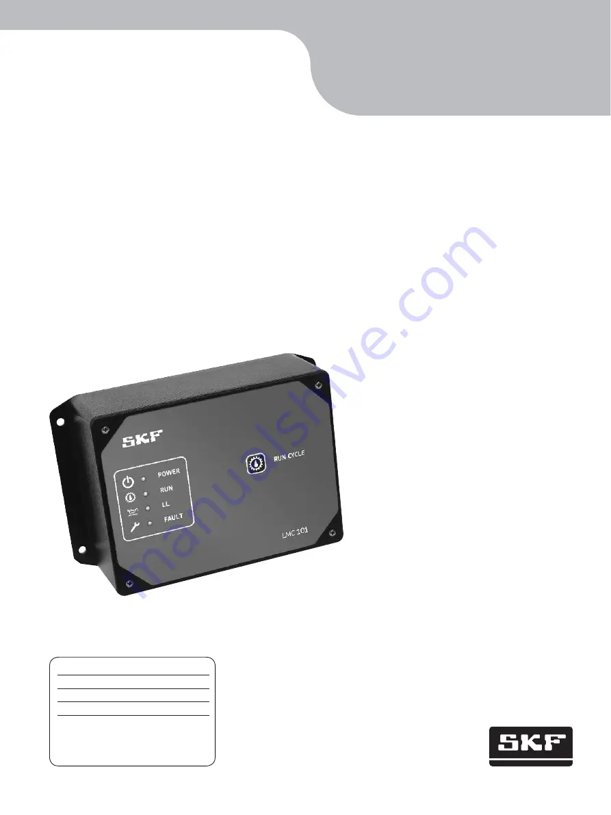
Single line and progressive
lubrication system controller
Model 86535
Date of issue
June 2015
Publication number 404416C
Section
C8
Page Number
350C
Installation and user guide
Страница 1: ...Single line and progressive lubrication system controller Model 86535 Date of issue June 2015 Publication number 404416C Section C8 Page Number 350C Installation and user guide ...
Страница 2: ... understanding all safety and operational instructions WARN IN G Notice Local safety regulations regarding installation use and maintenance must be followed Explanation of safety signals Indicates hazardous situation which if not avoided could result in minor or moderate injury C AUTION Indicates hazardous situation which if not avoided may result in death or serious injury WARNING Indicates hazar...
Страница 3: ...s no more lube cycles be attempted until fault is corrected Controller mode In controller mode lube cycle ends when pressure switch pressure transducer or piston detector actuates Single Line system In single line systems Pressure switches or pressure transducers can be installed at pump and or end of supply line System allows pressure to dissipate to end of supply line once pressure at pump is re...
Страница 4: ...talled 5 50MB of available hard drive space after Net 4 0 client installed Notice If PC does not have Microsoft Net Framework 4 0 client installed confirm PC meets these requirements before downloading Net 4 0 client to PC Processor 1 GHz Memory 512 MB Hard drive 1 5 GB Operating systems Windows 7 Windows 8 If PC meets requirements visit http www microsoft com en us download details aspx id 17851 ...
Страница 5: ...tach cover before using controller Notice LMC 101 software must be installed on a PC with a USB port prior to proceeding in this section 4 Wait for Run light to stop blinking before proceeding 5 On PC double click LMC 101 software icon 6 Follow instructions in Controller configuration section on page 6 to configure and customize controller Notice When USB cable is connected Run and Power lights on...
Страница 6: ...ent or other name that will uniquely identify system that will be controlling software Controller configuration Notice LMC 101 can only be configured via USB cable to a PC that meets all PC requirements listed on page 4 Notice Customer and Location fields are stored on PC and on controller If wanting to track pump history and activity from multiple controllers determine a naming convention prior t...
Страница 7: ...troller to PC Notice Manual adjustment of internal clock is not recommended if historical data tracking is desired Notice USB port number must be selected prior to completing step 3 1 3 3 1 4 To controller downloads selected or saved account settings to controller 3 1 5 Exit closes LMC 101 configuration window 3 2 Clock adjusts controller s internal clock 3 2 1 Click sync time to PC button fig 3 3...
Страница 8: ...mum pumping time defines amount of time each pump will send lubricant 4 4 Prelube mode controls pre lubrication activity see step 5 on page 9 4 5 Pulse active checkbox activates pump pulsing option during pump cycling as defined by pulse time interval text box 4 6 Pulsing time interval defines amount of time between pump pulses Notice If system is progressive skip to step 1 on page 14 Notice Pulse...
Страница 9: ... 10 6 1 3 Pressure transducer select if using transducer pressure measurement at pump to end lube cycle if selecting this option skip to step 8 on page 11 5 Prelube drop menu defines lubrication cycling option upon controller power up Always a prelube cycle will always occur during power up After 3hr off a prelube cycle will only occur when power has been off for longer than 3 hours Never a prelub...
Страница 10: ...te lubrication cycle 7 2 Pressure hold time allows lubricant pressure to dissipate in supply line after an elapsed amount of time Notice Pressure hold time option is only available when not using an end of line pressure switch A pressure switch or transducer must still be used at pump in End of Line systems to prevent pressure build up WA RN ING 10 ...
Страница 11: ...ems to prevent pressure build up 8 2 Pressure Hold Time Allows lubricant pressure to dissipate in supply line after an elapsed amount of time 8 3 Transducer radio button 1 to 6 V Transducer allows use of a 1 to 6 V transducer 4 To 20 mA transducer allows use of a 4 to 20 mA transducer 8 4 Max transducer pressure sets maximum pressure rating of transducer Software allows for input range of 0 To 400...
Страница 12: ...w if Pressure Transducer option selected 9 2 Pump pressure at which lube cycle ends If only using one pressure transducer lube cycle will end at this setting Notice For step 9 2 if using an End of Line pressure transducer pump will stop at this pressure level to allow dissipation of pressure in supply line Pump will restart once this pressure level drops below 25 of this setting 9 3 Line pressure ...
Страница 13: ...s will occur after a low level alarm 10 2 Pressure fault indicates that a pressure fault has occurred No more lube cycles after pressure alarm no more lube cycles will occur after a pressure alarm Continue to allow lube cycles after pressure alarm lube cycles will continue after a pressure alarm Limited number of lube cycles after a pressure alarm a set number of lube cycles will occur after a low...
Страница 14: ...me amount of time that pump will be allowed to remain active Range 15 seconds to 99 minutes 1 4 Prelube drop menu defines lubrication cycling when controller powers up Available options are Always a prelube cycle will always occur after power up After 3hr off a prelube cycle will only occur when power has been off for more than 3 hours Never a prelube cycle will not occur after power up 1 5 Pulse ...
Страница 15: ...witch actuation ends lube cycle 2 3 Proximity Number of proximity switch actuations per cycle Notice Proximity switch must actuate number of times entered in Pulses box during each lube cycle Failure of controller to detect number of actuations within defined maximum pumping time triggers alarm Notice For instructions on Alarm features refer to step 10 on page 13 15 ...
Страница 16: ...ecent 72 reports will be captured Older events will not be included 2 1 System button captures date and time for any system reset including each time a controller powers up a new configuration is saved to a controller 2 2 Lube cycles button captures date and time for each successful lube cycle 2 3 Alarms button captures date and time for each alarm that prevented cycling 2 4 Counters button captur...
Страница 17: ...y must connect to controller within 13 seconds If light continues to blink connection was successful Continue to next step If light stops blinking connection was unsuccessful Repeat steps 1 4 until light continues blinking 5 Click Find button 6 Navigate to latest code file Hex file 7 Highlight code file and click open 8 Click Update Firmware button 9 Wait until firmware update utility finishes 10 ...
Страница 18: ...d information on wiring connections figs 19 22 pgs 20 23 Notice Relieve tensile force on cables from outside of housing 1 3 2 5 7 6 8 9 10 4 Callout Description Callout Description 1 Control output actuator 4 relay outputs 1 electronic output 5 Screw 6 Button cell lithium battery 2032 7 USB type B 2 Input power and pump power 8 Cable gland for control inputs and outputs 1 2 in 12 7 mm diameter 3 3...
Страница 19: ...g 18 Dimensions 6 75 in 171 5 mm 3 5 in 88 9 mm Ø 0 19 in 4 8 mm 7 29 in 185 2 mm 4 72 in 119 9 mm 5 62 in 142 8 mm 6 12 in 155 5 mm 1 16 in 29 464 mm 1 50 in 38 1 mm 1 196 in 30 37 mm 1 50 in 38 1 mm 19 ...
Страница 20: ...l lube J Pressure switch at pump D Positive from battery K Pressure switch at EOL end of line E Vent solenoid L USB port F Low level alarm 24V VENT SOLENOID GND 2 1 1 2 4 3 LL FAULT 3 4 5 6 SYSTEM FAULT 7 8 9 10 SYSTEM FAULT 11 12 13 14 PRESSURE AT PUMP 17 18 19 20 PRESSURE AT EOL 21 22 23 24 MAN LUBE 15 16 Outputs To motor From battery Inputs Port M A Wire Power source Motor Switch Normal open US...
Страница 21: ...itive from battery M 4 20 ma pressure transducer at EOL E Vent solenoid N signal F Low level alarm O signal G System alarm P USB port H Reservoir low level I Remote manual lube 24V VENT SOLENOID GND 2 1 1 2 4 3 LL FAULT 3 4 5 6 SYSTEM FAULT 7 8 9 10 SYSTEM FAULT 11 12 13 14 PRESSURE AT PUMP 17 18 19 20 PRESSURE AT EOL 21 22 23 24 MAN LUBE 15 16 Outputs To motor From battery Inputs Port M A Wire Po...
Страница 22: ...escription Callout Description A Positive to motor from battery J 1 6 V pressure transducer at pump B Ground to motor K Power C Ground from battery L Output D Positive from battery M Common E Vent solenoid N 1 6 V pressure transducer at EOL F Low level alarm O Power G System alarm P Output H Reservoir low level Q Common I Remote manual lube R USB port Outputs To motor From battery Inputs Port M A ...
Страница 23: ...em using piston detector Callout Description Callout Description A Positive to motor from battery G System alarm B Ground to motor H Reservoir low level C Ground from battery I Remote manual lube D Positive from battery J Piston detector E Vent solenoid K USB port F Low level alarm Outputs To motor From battery Inputs Port M A Wire Power source Motor Switch Normal open USB data port Pressure Trans...
Страница 24: ...mbining products people and application specific knowledge SKF delivers innovative solutions to equipment manufacturers and production facilities in every major industry worldwide Having expertise in multiple competence areas supports SKF Life Cycle Management a proven approach to improving equipment reliability optimizing operational and energy efficiency and reducing total cost of ownership Thes...