


PiCAN FD Rev B 1.1
SK Pang Electronics Ltd
©
2017
www.skpang.co.uk
3
1.
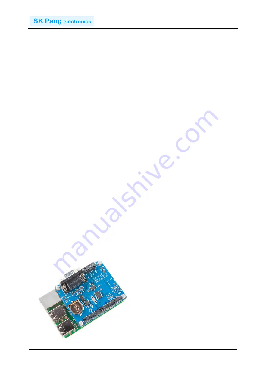
Introduction
This PiCAN FD board provide CAN-Bus FD capability for the Raspberry Pi 3. It uses the
Microchip MCP2517FD CAN FD controller with MCP2562FD CAN transceiver.
Connections are made via DB9 or 4 way screw terminal. This board is also available
with a 5v 1A SMPS that can power the Pi is well via the screw terminal or DB9
connector. A real time clock with battery back up (battery not included) is also on the
board.
Easy to install SocketCAN driver. Programming can be done in C or Python.
1.1.
Features
•
Arbitration Bit Rate upto 1Mbps
•
Data Bit Rate up to 8Mbps
•
CAN FD Controller modes
•
Mixed CAN2.0B and CANFD mode
•
CAN2.0B mode
•
Conforms to ISO11898-1:2015
•
High speed SPI Interface
•
CAN connection via standard 9-way sub-D connector or screw terminal
•
Compatible with OBDII cable
•
Solder bridge to set different configuration for DB9 connector
•
120Ω terminator ready
•
Serial LCD ready
•
LED indicator
•
Four fixing holes, comply with Pi Hat standard
•
SocketCAN driver, appears as can0 to application
•
Interrupt RX on GPIO25
•
RTC with battery backup (battery not included)
2.
Hardware Installation
Before installing the board make sure the Raspberry is switched off. Carefully align
the 40way connector on top of the Pi. Use spacer and screw (optional items) to secure
the board.


