


EN
34
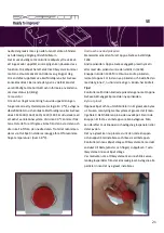
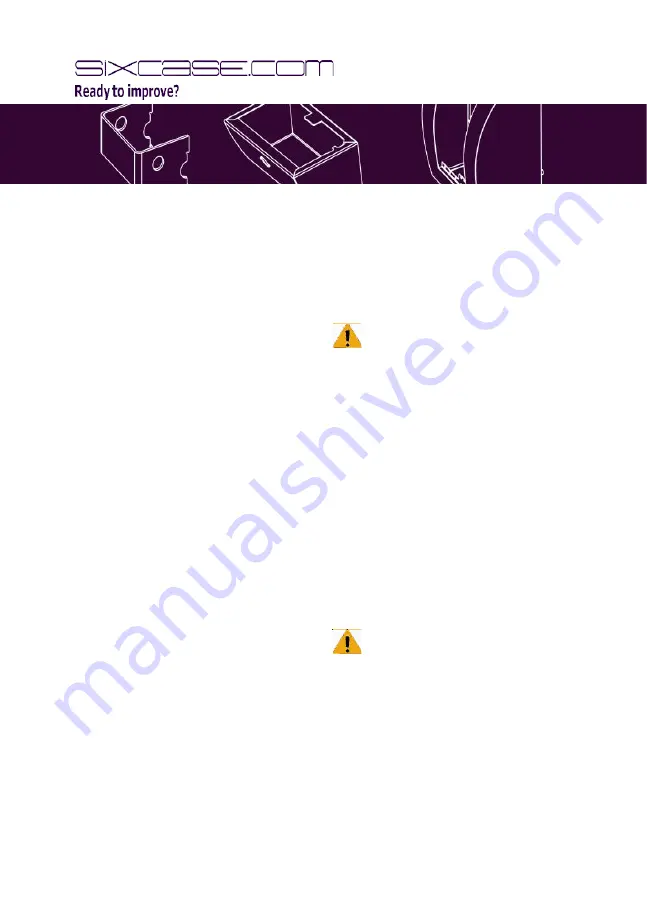
Feeder cable
SixCase also recommends drilling the 12 mm hole in such
a way that the feeder cable can be led through the wall.
It can then be attached to the 24V adapter, which should
be placed inside the house or building. It is important to
lead the feeder cable through the wall before mounting
the case on this wall. The cable contains a connector that
enables it to be attached to the SixCase. Lead the cable
from the outside through the wall to the inside and then,
from the inside, pull the cable until the connector touches
the wall. The metric wire can be led through the hole and
the SixCase is then ready to be mounted on the wall. After
mounting it, using the four nuts, the connector can also
be attached with a plastic wreck.
Be careful
If the wall is not very strong, we recommend to use
Fischer VS 100P. After spraying the fluid into the holes,
insert only the dowl screws
–
do not use the plugs again.
Read the instructions on the Fischer label carefully and
make sure that you clean the holes thoroughly after
drilling.
Mounting on wood
Drill small holes of approximately 4 mm diameter in the
wood and, using a tool, screw the dowel screws firmly
into the wood and then mount the SixCase as instructed
above. The screws should not extend more than 30 mm
from the wooden surface. We recommend drilling the
upper holes at a height of between 1.5 and 1.6 m from
the ground.
Mounting the SixCase
Hang the SixCase on the dowel screws you have just
installed in the wall and lock them with the four nuts from
inside the cabinet. The nuts can be tightened using a fork
spanner size 13. Be careful not to jam the feeder cable.
Operation
To close the cabinet, place both hands on the bottom left
and right-hand sides of the cabinet and push upwards.
Both locks (left & right) will then produce an audible click
as confirmation that the cabinet is locked properly on
both sides.
In case of emergency (usage AED)
SC1310: Push the red button (as shown on the
instruction sticker), wait until the bracket has reached its
lowest position and remove the AED.
SC1415: Insert key on the right under bracket (as shown
on the instruction sticker) and turn the key powerfully to
the right. Wait until the bracket has reached its lowest
position and remove the AED.
SC1420: Push the red button (as shown on the instructi-
on sticker), wait until the bracket has reached its lowest
position and remove the AED.
SC1320/ 1340/ 1435: Enter the programmed code or
insert key on the right and turn the key powerfully to
the right (as shown on the instruction sticker), wait until
the bracket has reached its lowest position and remove
the AED (both code and key must be available in case of
emergency).
Important
It is mandatory to always have the code, key and
SMS code available in case of an emergency (applies to
SC1435). Due to an unexpected defect it may happen
that one of the openings procedures fails. In this case it
is necessary to have an alternative available. Furthermo-
re, it is important to rehearse the above mentioned pro-
cedures before storing the defibrillator, and frequently
after having installed the AED.
Содержание SC1310
Страница 1: ...V22012016 ...
Страница 2: ...1 SC1310 1330 SC1320 1340 1 2 3 4 5 6 Control Unit Control Unit 7 8 ...
Страница 3: ...2 SC1420 SC1435 1 2 6 5 4 3 ...
Страница 17: ......
Страница 39: ......
Страница 54: ......


