


10
Operation
CUTTING
SERIES
EQUIPMENT
11
CUTTING
SERIES
EQUIPMENT
Operation
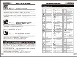
4.Cutting current adjustment
Clockwise rotate to enlarge the current
,
and anti-clockwise rotate to reduce the current
.
CAUTION
Loose welding terminal connections can cause
overheating and result in the male plug being
fused in the bayonet terminal.
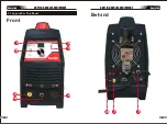
5. Positive Welding Output Terminal
The positive cutting terminal is used to connect the cutting output of the power source
to the appropriate welding accessory such as earth clamp. It is essential, however, that
the male plug is inserted and turned securely to achieve a sound electrical connection.
6. Plasma Torch Connector
Plasma torch insert in to connect with the machine. It’s necessary to be sure that the
plug is correctly and tightly connected to maintain the electricity and gas supply.
DO NOT TOUCH the electrode wire while it is
being fed through the system. The electrode
wire will be at welding voltage potential.
1. Digital Display
The digital meter is used to display the pre-set (preview) amperage for cutting and the
actual cutting current.
2. Power Indicator
The green power indicator will be illuminated when the welder is turned ON and indicates
the presence of power.
WARNING
7. Plasma torch control Switch
Remote control Switch receptacle is used to connect a plasma torch trigger switch:
To make connections, align keyway, insert plug, and rotate threaded collar fully clockwise.
The socket information is included in the event the supplied cable is not suitable and it is
necessary to wire a plug or cable to interface with the receptacle.
3. Thermal Overload Indicator Light
This welding power source is protected by a self resetting thermostat. The indicator will
illuminate if the duty cycle of the power source has been exceeded. Should the thermal
overload indicator illuminate the output of the power source will be disabled. Once the
power source cools down this light will go OFF and the over temperature condition will
automatically reset. Note that the mains power switch should remain in the on position
such that the fan continues to operate thus allowing the unit to cool sufficiently. Do not
switch the unit off should a thermal overload condition be present.
8. Power switch
before using the machine. Pull the switch to the closure state of “AN” to operate the
machine, and pull the switch to “AUS” after use. Turn off the power input, and the machine
will stop operating.
9. Gas input port
The gas port is connected with the gas valve output port. After connection, check whether
there is gas leakage. (As shown in the picture of section 3.2: Gas valve assembly)
10. Program downloading port
Change the program downloading connection port, and use the plastic cover to prevent
the dust from polluting and oxidizing the port after use.
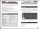
3.2 Installation Instructions
In order for the unit to function correctly, it must be installed properly. Follow the procedure
given below for correct installation:
1. Read the safety rules given in this manual carefully.
2. Check on receiving the unit that there are no defective parts or parts damaged during
transportation.
3. Attach air regulator as show in picture Air Regulator Installation only for Paris500.
4. Set your unit up in an area which is adequately ventilated and make sure that the air
vents are not obstructed.
5. Connect the power supply cable to a socket located as near as possible to the work area,
so that the unit can be switched off quickly in case of emergency.
6. Your machine has a 16 amp plug fitted, before use check that the green/yellow earth is
connected to the earth pin socket of fitted plug.
7. Make sure that the mains supply switch and any fuses have a value which ± 15% the
maximum current absorbed by the unit. All fuses should be the slow-blow type.
8. Any extensions of power supply cable should have the same cross-section as the power
supply cable. The extension leads, however, should only be used when absolutely
necessary. It is important to note that any extension of mains cables or torch cables will
possibly affect the cutting performance of this cutting equipment, due to the fact that the
resistance of the cable will reduce voltage input, which is determined by the length of the
cable. The supplied length of main cables and torch cables is recommended.
9. Fasten the earth clamp to the piece to be cut, If the surface of the piece to be cut is
painted, rusty or covered with insulating material, clean the surface so that
satisfactory contact between the piece and the earth clamp can be obtained.
10. Make sure that the torch has been assembled with the correct components and that the
cutting tip is suitable for the cutting current.


