9
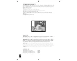
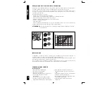
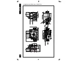
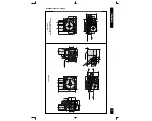
Flange connections (flanges shall be according ISO 7005)
First screw the pipes into the flanges and then the flanges to the multifunctional control.
Recommended torque for flange retaining screws: 3 Nm.
Caution: check the”0” ring is properly placed in the groove of the flange.
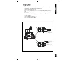
Rp 1/2 connection
Prevent foreign matter from getting into the valve during installation. In particular, check the cleanliness of the
inlet and outlet pipes.
The connection must be made using gas pipes with Rp 1/2 ISO 7 thread. Torque: 25 Nm.
Connection to the pilot burner (versions with pilot burner outlet)
4 mm, 6 mm or 1/4'' pipes can be used. Use appropriately sized nut and olive. Tighten to 7 Nm torque
.
WARNING
:
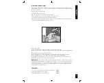
if you don’t use a pilot outlet provided device, you must seal it using optional code no. 0.972.041
Torque: 7 Nm.
ELECTRICAL CONNECTIONS
General precautions
All electrical connections must be made in accordance with current electrical standards. Check that the voltage and
frequency of the coils, given on the valve, are correct. Disconnect the power supply before starting installation.
Check that all connections, in particular the earth, are made properly.
To make this effective you have to use fast-on contact on the body, or a female contact of the connector with correct
characteristic (see EN 60730).
When you use connector, ensure that the fastening screws are never slack.
Automatic valves are powered with a male contact 3003 molex compatible, suitable for female Molex series 3001.
Electrical modulator is powered with a male fast-on connector 2.8 x 0.8 mm.
The 24 Vac versions must be powered by means of an insulating transformer (with very low safety voltage in
accordance with EN 60742). To connect, use AMP 1.1 x 1.1.
Make the connections as specified in the technical instructions for the flame failure device used and/or in the specific
standards for the appliance. The electrical safety cut-off devices (for example, the flame failure device, thermostat
etc.) must cut off the power supply to both solenoid valves simultaneously.
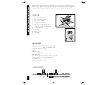
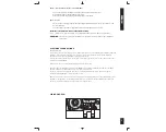
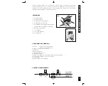
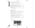
WIRING DIAGRAM
Pin
Po
Ve
P.R.A D J
.
1 2
3 4
EV1
EV2
ENGLISH
Содержание 840 SIGMA
Страница 2: ......
Страница 3: ...English GB 14 4 Italiano IT 25 15 ...
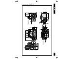
Страница 11: ...11 Gas connection G3 4 ISO 228 ENGLISH ...
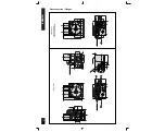
Страница 22: ...22 Collegamento con filetto maschio G3 4 ISO 228 ITALIANO ...
Страница 26: ...SIT Group www sitgroup it e mail mkt sitgroup it ...


