


17
9.3 Commissioning the actual-position feedback unit SISTO-SK-i LED/SISTO-SK-i LED AS-i with an integrated
solenoid valve - on site
1. Verify that the electrical and pneumatic connections were established properly.
2. Check the supply voltage and the control pressure present.
3. Check that the actual-position feedback unit is properly mounted on the valve actuator.
Start initialisation:
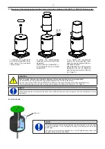
1.
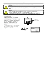
Keep the programming magnet in the middle of the top of the cover for at least 2 seconds. If the colour code start flashing yellow,
remove the magnet again.
2. The Actual-position feedback unit
switches the internal solenoid valve, reaches the both limit positions and saves them internally.
3.
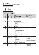
Limit position will be saved and signalled via colour code of LED. (Table “Colour code of high-visibility LED“, Section 7.1, Page 7)
Actual-position feedback unit is ready to be operated.
9.4 Commissioning the actual-position feedback unit SISTO-SK-i LED/SISTO-SK-i LED AS-i with an integrated
solenoid valve - remote initialisation
1. Verify that the electrical and pneumatic connections were established properly.
2. Check the supply voltage and the control pressure present.
3. Check that the actual-position feedback unit is properly mounted on the valve actuator.
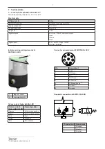
SISTO-SK-i LED procedure:
1. Start remote initialisation: Apply 24 volts to the teach-in input (pin 5) for at least 0.5 seconds.
2. The actual-position feedback unit actuates the internal solenoid valve, reaches the both limit positions and saves them internally.
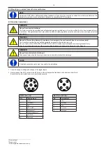
3. A signal is present at pin 2 (DO Open) or pin 4 (DO Closed).
4. No voltage is present at pin 7 (DO Fault).
(Table „Pin assignment“, Section 7.1, Page 7)
Actual-position feedback unit is ready to be operated.
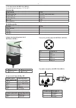
SISTO-SK-i LED AS-i procedure:
1. Start remote initialisation: Activate DO2 via AS-i master for at least 0.5 seconds.
2. The actual-position feedback unit actuates the internal solenoid valve, reaches the both limit positions and saves them internally.
3. A signal is present at DI0 (Open) or DI1 (Closed).
4. No voltage is present at fault output (DI3).
(Table „Inputs and Outputs“, Section 7.5, Page 10)
Actual-position feedback unit is ready to be operated.
9.5 Reset of the actual-position feedback unit to factory setting
•
Keep the programming magnet in the middle of the top of the cover for 30 seconds.
• Not initialized operating status is indicated by the blue colour code of LED
.
9.6 Shutdown
WARNING
Risk of injury!
Carry out work on the SISTO-SK-i LED/SISTO-SK-i LED AS-i actual-position feedback unit during standstill only.
ATTENTION
The installation be performed by skilled and trained personnel. Always use suitable tools to ensure proper functioning of the actual-
position feedback unit.
NOTE
All applicable accident prevention, health and safety regulations must be observed when working on electrical equipment.
Measures for shutdown:
▪ Before intervention in the system
:
1. The system must be de-energised.
2. Secure against restart.
3. Check that no voltages are present.
•
Before the air supply connections are released:
1. Feed line must be depressurised.
2. Feed line bleed.
3. Feed line secure against being re-pressurised.
9.7 Removing the actual-position feedback unit
The actual-position feedback unit is dismantled in reverse order.


