background image

Sirona Dental Systems GmbH

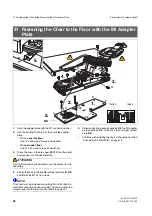
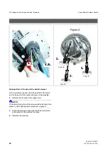
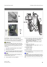
36 Reversing the Direction of the Travel Track 

59 58 470 D 3370
D 3370.031.01.10.02

49

båÖäáëÜ

ATTENTION 

Unplug the unit!

1.

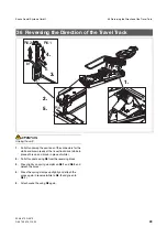
Pull off and swap the positions of the connectors for the 
white and brown leads at the travel track drive (white in 
place of brown and brown in place of white).

2.

Pull off socket casing 

R6

 from the reversing block.

3.

Press lightly on spring clamp 

A

 on 

R6.1

 and 

R6.2

 and 

detach the cores.

4.

Press the spring clamps up slightly and attach the 
cores again in reverse (white to 

R6. 2

 and green to 

R6.1

).

5.

Attach socket housing 

R6

 again.

36  Reversing the Direction of the Travel Track

1

2

3

A

R6.2

R6.1

R6

1.

2.

3.

4.

5.

br

Содержание C2+

Страница 1: ... OH fåëí ää íáçå fåëíêìÅíáçåë kÉï ë çÑW NMKOMMU båÖäáëÜ ...

Страница 2: ...ument This document describes how to perform the installation of the C2 dental treatment center The installation of optional equipment is described in detail in other documents For installing optional equipment please refer to the follow ing documents among others SIROLUX FANTASTIC Installation Instructions Order Number 51 55 556 SIVISION 3 Installation Instructions Order Number 59 58 421 SIVISION...

Страница 3: ...ection system 16 12 Electrical Connection 17 13 Fastening of the Chair to the Floor 18 14 Adapting the Dentist Element 19 15 Preparing Chair and Water Unit 20 16 Adapting the Water Unit 21 17 Water Unit Making Connections 23 18 Adapting the Assistant Element 24 19 Assistant Element Making Hose Connections 25 20 Valve set additional units Making the hose connections 26 21 Distributor and Fuse Box 2...

Страница 4: ...itches 39 30 For the Customer 40 31 Fastening the Chair to the Floor with the M1 Adapter Plate 42 32 Settings on Dentist and Assistant Elements 43 33 Changing Function on C Foot Switch 46 34 Demonstration Unit without Water Connection 47 35 Packing Position 48 36 Reversing the Direction of the Travel Track 49 ...

Страница 5: ...approved by Sirona are connected they must comply with the applicable standards e g IEC 60950 for information technology equipment and IEC IEC 60601 1 for medical electrical equipment In case of doubt contact the manufacturer of the system components ATTENTION Any person who assembles or modifies a medical electrical system complying with the standard IEC 60 601 1 1 safety requirements for medical...

Страница 6: ...ess 80µm 0 08mm Installation must be performed in compliance with the recommendations of the national installation require ments e g EN1717 DIN 1988 The water quality must comply with the national re quirements for drinking water The connection must be made to cold water Air quality Oil free dry and hygienically perfect air is required for driv ing the highspeed handpiece for cooling the burr driv...

Страница 7: ...ished floor 2 The suction and drain pipes must finish flush with the upper surface of the floor Permissible deviation 5 mm Internal diameter for both pipes 36 5 mm 3 The electric leads must project by at least 500 mm Supply above the floor Supply tube ends corner valves and leads are routed as shown for details see Mounting Template For the connection the retrofit kit for installation above ground...

Страница 8: ... stop position 4 Fit the backrest onto the sword from above 5 Fasten the backrest with the six screws removed under item 1 NOTE i With the electrical headrest the padding flap P is fastened with the two middle screws Never use washers ATTENTION Tighten all screws Screws that are not tightened can lead to functional disturbances when moving the headrest in and out 4 Installing the Narrow Backrest 5...

Страница 9: ...he head support to its stop position 5 Place the metal bracket tilted slightly backward onto point B and tilt the backrest forward 6 Retighten the backrest with the six screws removed un der 1 above NOTE i With the electrical headrest the padding flap P is fastened with the two middle screws Never use washers 7 Screw in screws A see ATTENTION and C ATTENTION When screwing in screw A make sure that...

Страница 10: ... 2 Place fork D on spindle nut E NOTE i Make sure spindle nut E is properly positioned Flat end of spindle nut facing fork D 3 Insert fork D in the slide of headrest G 4 Insert driving pin F from below and secure it with retain ing ring S 5 Remove cable ties 6 Remove the styrofoam transport safety device 6 Installation with Motor Driven Headrest D D E E 2 1 S F 4 G 3 i 5 6 ...

Страница 11: ...ctor X4 3 Pass connector X5 through hole H and plug in 4 Run tilt part cables with connector X3 through guide L to the board Plug in connector X3 5 Retighten cable clip I with screws G 6 Screw cover V of the distributor housing back on ATTENTION Make sure all hexagon cable sleeves fit properly 7 Interconnect connectors X1 and X2 floating connec tion and place them one after the other into the re c...

Страница 12: ... with washers 6 Loosen the bellows in the lower region 7 Separate the chair from the pallet Unscrew four fastening screws with washers 8 Remove lateral cover on each side NOTE i If the C2 is being assembled as a replacement for an M1 that was previously located at this position an adapter board can be ordered Order No 58 70 493 with which the existing mounting holes can still be used For installat...

Страница 13: ...ng lay er Y have to be overcome and a hole at least 80 mm deep has to be drilled in the load bearing concrete Z for a secure anchorage ATTENTION Floor heating Determine the position of the heating coils with the heating turned on 2 Drill the dowel holes ATTENTION DO NOT use dowels for wooden floors With wooden floors provide appropriate supporting beams and make the nec essary arrangements With wo...

Страница 14: ...and H after the electrical connection has been made The chair can then be moved upward with the foot control refer to page 18 ATTENTION The chair base must be exactly adjusted to the horizontal position For compensating any unevenness in the floor shim ming plates contained in the package can be used More shimming plates can be ordered by quoting the following order numbers 1 mm Order No 47 09 304...

Страница 15: ...Connect the flexible connecting pipes for water green marking and air blue marking to the on site corner valves Screw seals tight with nuts ATTENTION Use only properly fitting open jawed wrenches for installa tion Never use pipe wrenches Observe the permissible bending radius and avoid sharp bends Never twist the hoses Also make sure that unintentional twisting does not occur when tightening down ...

Страница 16: ...tors GN and YE from MV1 and in sulate 2 Turn coil F of MV1 slightly and pull off 3 Loosen screws D and remove MV1 4 Insert two new O rings and set pressure regulator AD3 into place correctly positioned Attach firmly with screws A Be careful with the O rings NOTE i Pressure regulator AD3 is included in the water unit pack age 5 Undo two screws B and remove nipple holding plate 6 Remove plug C and a...

Страница 17: ...l points for key for example composite function of the ceiling model SIROLUX FAN TASTIC when present With the SIROLUX FANTASTIC ceiling model two ca bles have to be laid from the ceiling to the installation tube in the connection area of the chair Note setting as switch or push button momentary See Operating Instructions chapter Basic Work station Settings Mode Key ATTENTION The control voltages c...

Страница 18: ... foot control Ob serve Operating Instructions 3 Fasten the chair to the floor with two wood screws and washers With a concrete floor Use 10 x 200 wood screws With a wooden floor Use 10 x 110 wood screws With the M1 adapter plate refer also to page 42 Use M 10 x 40 4 Switch the main switch off 13 Fastening of the Chair to the Floor 58 71 848 D3370 58 71 848 D3370 1 2 3 4 C H 10x200 2 ea 10x110 2 ea...

Страница 19: ...ring the ad justment 4 Tighten the screws Check the levelness of the dentist element head with a spirit level at different places on the track If necessary loosen the screws again remove the spacer plate and repeat the process until the dentist el ement stands level 5 Put on the tray support NOTE i If the customer wishes to have the dentist element in the neutral position at the head end of the ch...

Страница 20: ...e hoses are arranged as shown in the drawing Remove protective bag from connector and cable ties K 5 Check to make sure that the electrical leads have been routed through the other opening in the stand and through the cable holders 6 Remove both covers carefully To do this place a screwdriver in recess A to carefully prize the two hous ing covers apart 7 Grease O rings and insert tumbler faucet up...

Страница 21: ...e cover A and unscrew the sheet metal support for the video components 4 screws Lay suction and drain hoses through Then reattach cover A and the sheet metal support 2 Fasten the water unit to the chair base with two screws D M8x20 and washers do not tighten yet 16 Adapting the Water Unit 58 71 848 D3370 58 71 848 D3370 D D 2 A 1 1 M8 screw 2x ...

Страница 22: ... Tighten screws A 7 Tighten the nuts of screws F 8 Pull hoses and cables into the junction box area of the chair NOTE i Adapt the length of the suction and drain hoses to suit local conditions Cut off pieces of superfluous hose if any 9 Grease O rings and insert the end piece of the drain hose small hose diameter and of the suction hose large hose diameter ATTENTION Make sure that the suction pipe...

Страница 23: ... lead into correspond ingly marked recess of terminal box Plug in connector 3 Connector X7 and cable X1 Plug connector X7 into fuse board CF Connect gray GY cable onto X1 1 board CF and pink PK cable onto X1 2 ATTENTION Make sure you connect the cables the right way around 4 Insert cable through recess in fuse box and fasten with washer A 5 Remove connector housing X8 jumper with marking tag from ...

Страница 24: ... compensated for by an empirically determined combination of spacer plates 5 Tighten the screws Check with a spirit level to make sure that the assistant element head is level If necessary loosen the screws again remove the spacer plate and repeat the procedure until the assis tant element is level 6 Close the cover again NOTE i The adjustment of the height and swivel stop settings of the support ...

Страница 25: ... Refit the nipple holder ATTENTION Make sure that the nipple holder is firmly seated in the guide grooves of the hose nipples Check by pulling on the nip ples Stow the manifolds in the rear bottom area 3 Attach the nipple of the hose W43 to its matching coun terpart Snap on the safety clip 4 Attach the nipple of the hose A34 to its matching coun terpart Snap on the safety clip NOTE i Step 4 also a...

Страница 26: ...e nipple holder Version without disinfection system 1 Unscrew hose W52 from quick coupling A water con nection and pull it off 2 Shorten hose W52 to a length of 310mm 3 Plug hose W52 into quick coupling A water connec tion and screw it tight 4 Unscrew the closing plate from the valve block Remove the blind nipple insert hose W52 and screw it onto the closing plate 20 Valve set additional units Mak...

Страница 27: ...ohmmeter to measure resistance between points B and C The value must be ATTENTION Due to the relevant EMC regulations the distributor box and all electrical parts must be isolated from all grounded points NOTE i If in addition a unit lamp tray and or Tray with SIVISION 3 monitor have been ordered they should be installed now refer to separate installation instructions 21 Distributor and Fuse Box 1...

Страница 28: ...h down 4 Slide both aluminum profiles over protrusions B in housing cover Fasten screws A tight 5 Insert the two side covers in tongue and groove joint 6 Remove the cover from the front housing Attach front housing cover inserting it in side covers First screw on upper screw D loosely lining up coupling nut if necessary ATTENTION Make sure that cables and hoses are not pinched behind the domed nut...

Страница 29: ...0 D 3370 D 3370 031 01 10 02 29 båÖäáëÜ 8 Remount bottom part of amalgam separator 9 Sever the cable tie on the motor of the amalgam sepa rator 10 Slide transport brace with cable tie downward and re move to the rear through opening in chassis 11 Put on the cup support 8 9 10 11 ...

Страница 30: ...9 58 470 D 3370 30 D 3370 031 01 10 02 12 Note Serial No for Unit Passport 13 Insert and engage folding cover 14 Attach inner housing cover at an angle so that it snaps in place ATTENTION The housing cover must be seated above the lateral tube connector Serial No 12 14 13 ...

Страница 31: ...rame and press it on with form fit 2 Slide in side housing covers NOTE i Make sure that the housing bearing with the correct serial number is installed For comparison purposes check the serial number that is affixed to point S 3 Use two screws and washers to screw on upper cover plate 4 Plug on faceplate Attach the bellows to the foot control 5 When using foot switch C Screw on retaining bow of fo...

Страница 32: ...cable for SIROTOM and fasten with screws or plug the video camera into the rear panel of the dentist element Attach the corresponding handpieces 7 Fit the instrument hoses on the assistant element ac cording to order from the left to the right Plug in the Mini L E D or the hose for surgical suction or SIROCAM 3 C Plug on and screw down the hose for SPRAYVIT Plug on the suction hose with the upper ...

Страница 33: ... the backrest padding NOTE i For details see the paper slip on the upholstery 4 Hook the padding onto the two upper studs ATTENTION Risk of upholstery damage Do not let the upholstery come into contact with edges B when fitting it 5 Pull the upholstery backing in the lower fastening area downwards and hook it over the lower studs 6 Affix the adhesive strips of the Velcro strap by pressing them ont...

Страница 34: ...ook the padding onto the two upper studs with Torx screws 5 Pull down the padding backing in the lower hooking ar ea do not let the padding come into contact with edges A and hook it onto the lower studs 6 Press the padding to the right and left sides over the outer contour of the rear cover while holding the cover back with your hand The padding snap fasteners B must snap into place The edge cont...

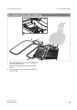
Страница 35: ...1 01 10 02 35 båÖäáëÜ 1 First press the padding snap fasteners E carefully until they snap into the clamp D Then insert the seat padding at the foot area into the bracket 2 Lay the protective cover on top and press uniformly on the Velcro strap 26 Installing the Seat Padding E 1 2 D 1 ...

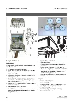
Страница 36: ...page 6 Initiate tumbler filling see Operating Instructions 7 Initiate cuspidor rinsing see Operating Instructions 8 Cuspidor rinsing adjustment Fold open the cover flap on the base Adjust control nozzle B by turning the knurled wheel until the bottom of the cuspidor bowl is rinsed evenly Close cover flap again 9 If the customer wishes the factory set suction power can be adjusted at control nozzle...

Страница 37: ...he 4 on 1 probe Order No 36 66 336 Factory settings for running turbine Turbines T1 Control TC1 and TC3 TM1 TITAN Propellant air shown on the display 3 5 bar 0 1 bar Propellant air at 4 on 1 probe TL 2 7 bar 0 1 bar Spray air at 4 on 1 probe SL 2 7 bar 0 1 bar EL 1 motor SL The cooling air pressure for the motor results from the driv ing air setting of the turbine A turbine has to be fitted instea...

Страница 38: ...hose Start the turbine with the foot switch Set the pressure of the propellant air at RD5 with a screwdriver Do not undo the screw further than to the level of the plastic collar Repeat setting for other holders Close the unit head Take out the instruments and remove the instru ment tray Fold down the unit head and install screws B When installing the unit head make sure that is centered with resp...

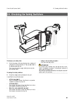
Страница 39: ...t the leg support The chair movement stops then there is a corrective movement upwards for about 3s Lift the backrest The backrest movement stops then there is a correc tive movement upwards for about 3s Raise the motor adjustable headrest The backrest movement stops then there is a correc tive movement upwards for about 3s Swing in the swiveling cuspidor The chair movement stops ATTENTION If one ...

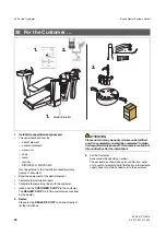
Страница 40: ... customer records kept by the dealer 2 Dealer Please fax the DEALER S COPY to Sirona directly af ter the installation ATTENTION Please note that any warranty claims can be fulfilled only if the completely and legibly completed Installa tion report warranty passport document is available at Sirona directly after the installation 3 For the Customer Accessories depending on order The accessories show...

Страница 41: ...ve to ini tiate sanitization If the customer does not need the station for patients until later the customer has to sanitize the water system one day before using the station 5 Technical documents Keep the CUSTOMER S COPY of the unit pass port together with the other technical documents The operating instructions supplied with the treat ment instruments should be kept in the plastic jakket provide...

Страница 42: ... chair by its backrest or by the bracket for the upholstery 4 Fasten the chair to the adapter plate at points A B D E and K with the M10 x 18 screws NOTE i The chair must be fastened at positions C and H after the electrical connection has been made The chair can then be moved upward with the foot control refer to page 18 5 Screw protective ground conductor S to the M1 adapter plate and the bottom...

Страница 43: ... Elements If the customer so wishes the height setting on the dentist and assistant elements can be readjusted NOTE i Lift the support arm slightly to loosen the adjusting screw 1 Loosen the adjusting screw 2 Adjust to the height desired by the customer or in keep ing with room conditions 3 Retighten the adjusting screw 32 Settings on Dentist and Assistant Elements 1 3 2 ...

Страница 44: ...ect of the rotary joint at the head of the dentist element can be adjusted 4 Remove the covering of the support arm NOTE i To illustrate the position of the setscrews A more clearly the brake is shown without attachment parts in figure X 5 Adjust the setscrews A equally until the braking force corresponds to the customer s wishes 6 Reattach the covering Figure X A A A Torx 15 Torx 15 Torx 15 4 6 5...

Страница 45: ... it will go NOTE i To illustrate the point the figure shows the support arm without paneling for steps 9 to 12 9 Loosen screw B Push stop pin upwards 10 Turn the support arm so that one screw of the end stop can be seen through hole C or D Loosen screw Continue rotating the support arm until the second screw can be seen Loosen screw Adjust the first stop in accordance with customer s wishes 11 Tig...

Страница 46: ...r the functions by operating the pedal at B the slide switch S5 in the foot switch can be changed as follows 1 Fold up the rubber hood at the front right corner of the pedal 2 Using a screwdriver push the slider of switch S5 to the right hole in the pedal 3 Reattach the rubber cover Press the knobs C tightly into the holes ATTENTION The complete edge of the rubber hood must be turned over the seal...

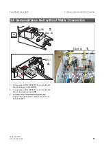
Страница 47: ...T power supply leads from dentist element board ADX 2 Unplug connector X5 of SPRAYVIT power supply leads from assistant element board HP 3 For water unit with disinfection system only Strip and insulate the electric cables in the chair at so lenoid valve MV1 34 Demonstration Unit without Water Connection gn ge L N gn ge L N X5 MV1 1 2 3 X5 Ass el Dent el ...

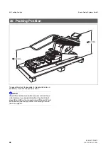
Страница 48: ...tation to an exhibition move it to the position shown NOTE i Should the chair be moved after the water unit and the as sistant element are already dismantled the short circuit plugs X8 and X90 on the connection box PC board CJ must be reinserted see chapter Water Unit Making Connec tions on page 23 35 Packing Position 650 mm 300 mm ...

Страница 49: ...ads at the travel track drive white in place of brown and brown in place of white 2 Pull off socket casing R6 from the reversing block 3 Press lightly on spring clamp A on R6 1 and R6 2 and detach the cores 4 Press the spring clamps up slightly and attach the cores again in reverse white to R6 2 and green to R6 1 5 Attach socket housing R6 again 36 Reversing the Direction of the Travel Track 1 2 3...

Страница 50: ...ä póëíÉãë dãÄe OMMT péê ÅÜÉW ÉåÖäáëÅÜ mêáåíÉÇ áå dÉêã åó a PPTMKMPNKMNKNMKMO NMKOMMU ûKJkêKW NNM SQQ fãéêáã Éå ääÉã ÖåÉ páêçå aÉåí ä póëíÉãë dãÄe áå íÜÉ rp W c Äêáâëíê É PN SQSOR _ÉåëÜÉáã dÉêã åó ïïïKëáêçå KÅçã páêçå aÉåí ä póëíÉãë ii QUPR páêçå aêáîÉI pìáíÉ NMM Ü êäçííÉI k OUOTP rp lêÇÉê kç RV RU QTM a PPTM ...

Отзывы: