Simrad NSO Скачать руководство пользователя страница 58

StructureScan | 57

Changing the StructureScan image

Zooming

You can select different zooming levels on the 
StructureScan image.

By default the zoom level is set to Off.

The range

The range setting determines the water depth that 
is visible on the screen

Auto

Auto mode will automatically set the range depending on the depth of water. Auto range 
will automatically be turned off once you adjust the range manually.

Manually changing the range

You can increase or decrease the range by pressing the zoom keys. 

Pressing and holding one of the zoom keys will toggle between auto and manual range. 
Autorange is resumed by pressing the “0” key.

When manually changing the range the upper depth line will always be at the water 
surface. This option allows you to focus on echoes at the upper part of the water column.

The frequency

StructureScan supports two frequencies. 455 kHz is ideal for greater depth penetration, 
while 800 kHz provides better definition especially at shallower depths. 

Clarity

Wave action, boat wakes and temperature inversion can cause on-screen clutter near the 
surface.

The clarity option reduces surface clutter by decreasing the sensitivity of the receiver 
near the surface.

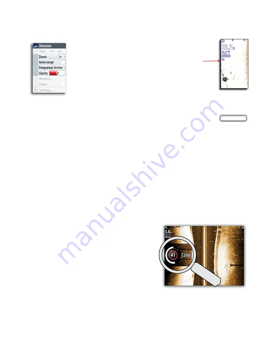
Adjusting the color settings

Strong and weak echo signals have 
different colors to indicate the different 
signal strengths. The colors used 
depend on which palette you select.

The more you increase the Color 
setting, the more echoes will be 
displayed in the color at the strong 
return end of the scale.

Color is adjustable by using the rotary 
knob. When you press the knob the 
color control image will expand and 
display it’s name in full. You can then 
adjust the value by turning the knob. 
If no adjustments are made within 3 
seconds the control will return to default 
size.

SELECTED 

ZOOM 

LEVEL

IN

OUT

Содержание NSO

Страница 1: ...www simrad yachting com A brand by Navico Leader in Marine Electronics Operation Manual Simrad NSO Multi function Display English...

Страница 2: ...olding AS and its subsidiaries branches and affiliates reserve the right to make changes to specifications without notice Copyright Copyright 2011 Navico Holding AS Warranty The warranty card is suppl...

Страница 3: ...3 s Press and hold on illustrated key with time indication Rotate rotary knob Single short press on rotary knob References to keys on the operator panel are written in boldface e g WIN key The softwa...

Страница 4: ...ages and panels 14 3 Using the simulator 15 Simulator mode 15 Demonstration mode 15 15 Advanced simulator settings 15 4 Charts 17 The chart panel 17 The vessel symbol 18 Extension Lines 18 Using the c...

Страница 5: ...ceiving MMSI messages 44 44 Target alarm settings 45 Viewing information about targets 45 Finding other AIS vessels 46 8 Using the echosounder 47 Setting up the Echosounder panel 47 Zooming 49 Adjusti...

Страница 6: ...avigating with the NSO 70 Sailing with the autopilot 72 Wind steering and navigation 74 Control of steering performance 74 Using the NSO in an AP24 AP28 system 75 Using the Autopilot in a EVC system 7...

Страница 7: ...ne modes 99 CZone system overview options 100 The BEP CZone info panel 100 17 Customizing your system 101 Page setup 101 Adjusting panel size 103 Setting the appearance of the instrument bar 103 Chang...

Страница 8: ...knob The function of the knob is depending on active context 9 X key cancels changes and returns to previous menu level 10 Cursor keypad used to move the cursor on the display and to maneuver in the...

Страница 9: ...e configured with some commonly used pages and you can also define your own pages Refer the Customizing your system section Chart page group example Radar page group example Panels Each application co...

Страница 10: ...s menu accessed by pressing the MENU key twice It provides access to system settings advanced settings for each function and for vessel specific settings Context menus A context menu contains items th...

Страница 11: ...nformation or entry different keys are used to confirm cancel and close the dialog Alarm messages The NSO system will continually check for dangerous situations and system faults while the system is r...

Страница 12: ...AND BY POWER OFF 2 PWR 1 DISPLAY PWR PWR 3 s On multiple processor systems the processor to power up must be selected prior to pressing the PWR key There is 5 second delay before an image will appear...

Страница 13: ...is included and optimized for low light conditions Details on the chart may be less visible when the Night mode is selected Operating the menu system You operate a menu by using the rotary knob to sel...

Страница 14: ...n a field is highlighted Adjusting values You adjust a numeric value in a field by using the keypad the arrow keys or the rotary knob You need to press the rotary knob first to change the function fro...

Страница 15: ...n you can have multiple panels but only one panel can be active at a time You will only be able to access the context menu of the active panel The active panel is outlined with a red border You can sw...

Страница 16: ...a files to be used by the simulator A set of source files is included in your system and you can import files by using an SD card inserted into the unit s card reader Refer to Pages section You can al...

Страница 17: ...16 Simulator Blank page...

Страница 18: ...a radar image and display AIS targets and weather information Simrad NSO comes preloaded with regional cartography US Versions include InsightHD Cartography for the entire US with Shaded Relief Europe...

Страница 19: ...rt panel The cursor by default is not shown on the chart panel When you press one of the arrow keys the cursor will become visible and the cursor position window will be activated When you are in curs...

Страница 20: ...from cursor position by pressing the Tick key You terminate the measuring function by pressing the X key Chart scale You zoom in and out in the chart by using the IN OUT keys or by using the rotary k...

Страница 21: ...he panel The chart orientation symbol in the panel s upper right corner indicates the north direction North up Displays the chart with the north direction upward Corresponds to the usual orientation o...

Страница 22: ...ed relief option presents chart including terrain information 2D Shaded relief Chart overlay Radar and weather information can be displayed as overlay on your chart panel When one of the overlay optio...

Страница 23: ...row keys but you cannot rotate the camera horizontally Cursor mode This mode includes two different options for moving the camera Camera Pan and Camera Rotate You switch between these two camera modes...

Страница 24: ...parency sets the opaqueness of the photo overlay Navionics Fish n Chip NSO supports Navionics Fish n Chip US only Fish n Chip provides high resolution bathymetric data Fish n Chip data is standard on...

Страница 25: ...tion chart and wording for either International or US presentation types Chart details Provides you with different levels of geographical layer information Safety depth The Navionics charts use differ...

Страница 26: ...a waypoint at the vessel position from any panel by pressing the PLOT key Short press activates the Plot menu allowing you to specify waypoint details in the Waypoint dialog Press and hold plots a way...

Страница 27: ...vessel allowing you to retrace your travel A track can later be converted to a route in the Tracks dialog described later in this section From the factory the system is set to automatically track the...

Страница 28: ...n is indicated on top of the panel until the route is saved The route can also be created from the Routes list as described later in this section Editing a route by using the cursor You can edit a rou...

Страница 29: ...t functions and settings for all these items available on your system There are several ways to access the library A couple of them are illustrated below You move between the tabs in the library by us...

Страница 30: ...sting 2D chart views and 3D for Navionics Refer to the Chart section The radar panel RANGE MARKERS RANGE RINGS NORTH INDICATOR ROTARY CONTROLS RANGE ORIENTATION MOTION DATA BAR HEADING LINE COMPASS IO...

Страница 31: ...mit Off and confirm with the Tick key Setting up the radar image Positioning the radar center You can move the radar PPI center to different positions within the radar panel The following options are...

Страница 32: ...el Setting the radar orientation Heading up Rotates the radar image to display the current heading directly up on the radar image North up Rotates the radar image with the north direction upwards Cour...

Страница 33: ...in value by turning the rotary knob when it is in manual mode Sea clutter Sea clutter is used to filter the effect of random echo returns from waves or rough water near the vessel When you increase Se...

Страница 34: ...radar operational functions are available from the Chart page s context menu More information on Radar Overlay is available in the Chart section of this manual Setting a guard zone around your vessel...

Страница 35: ...chart and radar image section Target tracking Targets visible on the screen can be tracked by the MARPA function Mini Automatic Radar Plotting Aid NOTE MARPA requires heading data for both the radar a...

Страница 36: ...ring that surrounds the vessel The EBL VRM function is used to measure distance and bearing from the vessel s position to a target Two different EBL VRMs can be placed on the radar image Positioning...

Страница 37: ...ansmit on one radar at a time e g Broadband Radar a distance and to trigger Racons Initial setup 1 Power up the system including both radars 2 On any display the first radar detected by the display wi...

Страница 38: ...el it is possible to set up different radar sources for each panel 6 The radar source selection is not global so it will only apply to the display on which the source was selected The radar source wil...

Страница 39: ...s A and B Range and radar controls for each virtual radar source are fully independent and the source can be selected for a particular chart or radar panel in the same manner as dual radar described i...

Страница 40: ...rols Broadband 4G Radar has several controls not found on any other Navico radar Target Separation The Target Separation control allows you to control the target discrimination of the radar as illustr...

Страница 41: ...The default is 30 for less clutter on the screen If OFF is selected for NSE NSO and Zeus the range performance is about equal to our 3G radar In some areas where extreme high interference may exist tr...

Страница 42: ...ROUGH STC Curve settings are available in the Radar options menu to better optimize the radar image to your liking Reset Device ID It is not necessary to reset the radar device ID for dual radar opera...

Страница 43: ...42 Using radar Blank page...

Страница 44: ...anel Target symbols The NSO system use the target symbols shown below Symbol Description Sleeping AIS target not moving or at anchor Moving and safe AIS target with course extension line Acquiring MAR...

Страница 45: ...argets either as true motion in the chart or relative to your vessel Sets the orientation of the AIS icon either based on heading or COG information Receiving MMSI messages You need to have your own M...

Страница 46: ...ange this will trigger an alarm Vessel message Controls whether an alarm shall be activated when a message is received from an AIS target MARPA target lost Controls whether an alarm shall be activated...

Страница 47: ...essels on chart and radar image Finding other AIS vessels You can search for other vessels equipped with suitable AIS devices from your chart menu or from the or feature in the Pages panel refer to th...

Страница 48: ...ges on off individually See The Echosounder settings panel later in this chapter Setting up the Echosounder panel The echosounder panel is setup from the panel s main menu The range The range setting...

Страница 49: ...ll see this as reduced distance between the zoom bars Bottom lock The bottom lock mode is useful when you want to view echoes close to the bottom In this mode the left side of the panel shows an image...

Страница 50: ...ge However a higher gain setting may introduce more background clutter on the image Conversely if the gain is set too low weak echoes may not be displayed Auto gain The Auto gain option will keep the...

Страница 51: ...far right side it indicates that you are viewing the latest soundings If you move the cursor to the left side of the screen the history bar will start scrolling towards left and the automatic scrolli...

Страница 52: ...from The echosounder settings panel see later in this chapter The following options are available Bytes per sounding Select how many bytes per second that are to be used when saving the log file More...

Страница 53: ...s recorded in the selected echo file you can select which channel and StructureScan image to display You exit the replay mode by pressing the X key Echo options Palettes Several display palettes with...

Страница 54: ...ibed on Adjusting color and gain settings For more information about StructureScan see StructureScan chapter 9 The Echosounder settings panel The echosounder source If you have more than one echosound...

Страница 55: ...Scan options See StructureScan overlay described previously Recording and viewing the echosounder data Refer page 5 _ Search depth Noise may cause the echosounder to search for unrealistic depths By a...

Страница 56: ...can is accessed via the ECHO DAK when the StructureScan external box and transducer are fitted ECHO x2 StructureScan can also be set up in one of the other page groups accessed by the DAK keys It can...

Страница 57: ...ER RANGE LOWER RANGE DEPTH TEMPERATURE FREQUENCY ZOOM COLOR INDICATOR SEA BED RANGE SCALE The SideScan image DEPTH TEMPERATURE FREQUENCY ZOOM COLOR INDICATOR WATER DEPTH RANGE SCALE LEFT WATER COLUMN...

Страница 58: ...ater column The frequency StructureScan supports two frequencies 455 kHz is ideal for greater depth penetration while 800 kHz provides better definition especially at shallower depths Clarity Wave act...

Страница 59: ...nction when the sounder image is paused Use the following process to measure a distance 1 2 Start the Measure function 3 Move the cursor towards the second measuring point A line will be drawn from th...

Страница 60: ...or on to an SD card inserted into the unit s card reader The following options are available Bytes per sounding Select how many bytes per seconds that are to be used when saving the log file More byt...

Страница 61: ...ally at the bottom of the screen The graphics below shows that both conventional echo sounder and StructureScan data are being logged RECORDING SYMBOL LOGGING MESSAGE The sounder recording is stopped...

Страница 62: ...more than one channel was recorded in the selected echo file you can select which channel and StructureScan image to display You exit the replay mode by pressing the X key StructureScan overlay You ca...

Страница 63: ...62 StructureScan Blank page...

Страница 64: ...e You remove the pop up from a page by pressing the X key The autopilot popup shows active mode heading rudder and various steering information depending on active autopilot mode The pop up has a fixe...

Страница 65: ...pilot If the NSO unit is part of an AP24 AP28 system the unit can be locked from the AP24 AP28 control unit Refer to Locking remote stations at the end of this chapter The autopilot panel The autopil...

Страница 66: ...ing x Changes commanded value x x Keeps the boat on a straight bearing line Heading speed position Dodging x x Resumes NoDrift mode after a heading change x x waypoint location or through a route of w...

Страница 67: ...rol of the wheel You return to STBY mode by a short press on the STBY AUTO key AUTO mode auto compass When the AUTO key is pressed the autopilot selects the current boat heading as the set course The...

Страница 68: ...ions except the C turn have settings that you may adjust before you start a turn and at any time when the boat is in a turn Refer to the example above U turn U Turn changes the current set course to b...

Страница 69: ...n a zigzag pattern you set the initial course change before the turn is started During the turn you can alter the course change and the leg distance The main course can be changed by turning the rotar...

Страница 70: ...low a depth contour Do not use this feature unless the seabed is suitable Do not use it in rocky Slope Narrow channel Ridge Use the following process to initiate DCT steering 1 Ensure that you have de...

Страница 71: ...while in NoDrift mode Dodging If you need to avoid an obstacle when using NoDrift mode you can press STBY and power steer or use the helm until the obstacle is passed If you return to NoDrift mode wi...

Страница 72: ...en selecting NAV mode the pilot maintains the current set course and prompts the user to accept the course change towards the destination waypoint The waypoint arrival circle The Arrival radius define...

Страница 73: ...and the wind transducer at the moment the WIND mode is selected From that point the autopilot will change the course to maintain the wind angle as the wind direction may change Tacking The tack functi...

Страница 74: ...e within control Tack and gybe prevent You should use the autopilot with care when beating and running If the sails are unbalanced when beating yaw forces from the sails can drive the boat into the wi...

Страница 75: ...The speed at which the autopilot automatically changes from LO to HI parameters is determined by the transition speed setting At no speed input the autopilot defaults to LO steering parameters when e...

Страница 76: ...HI LO parameter set based on speed motor boats or speed and wind sail boats You can however select to manually set which parameter set that shall be used HI or LO must be selected if no speed input i...

Страница 77: ...the steering irrespective of the autopilot mode The mode indicator on the pilot pop up will be replaced by a dash to indicate EVC override The system will return to NSO control in standby mode if no r...

Страница 78: ...y panel by moving the cursor to the position you wish to navigate to and pressing the GOTO key The go to cursor option will only be available when the cursor is active on a Chart Radar or Echosounder...

Страница 79: ...this radius Off course limit This parameter defines the vessel s accepted offset distance from the leg If the vessel goes beyond this limit an alarm will be activated Off course alarm must be enabled...

Страница 80: ...xt waypoint The course line When travelling on a route the course line shows the intended course from one waypoint towards the next When navigating towards a waypoint cursor position MOB or an entered...

Страница 81: ...80 Navigating Position panel Position in lat and lon Time and date SOG Speed over ground COG Course over ground...

Страница 82: ...Instruments 81 12 The Info panels INFO Instrument panels The J J Instrument dashboard styles J Adding dashboards...

Страница 83: ...82 Instruments Time plots J J J J Missing Data...

Страница 84: ...Instruments 83 Customizing the info panels You can J J J Edit an Instrument dashboard J Edit a Time plot layout J...

Страница 85: ...Blank page...

Страница 86: ...mal menu operation You switch between different tabs in a page by using the arrow keys You can also access a page by using the numeric key as indicated on each icon Any listing in the Pages panels has...

Страница 87: ...By pressing the MENU key you get access to available options for the selected item Waypoints routes tracks List of waypoints routes and tracks with details Trip Log Trip 1 Trip 2 Displays voyage and...

Страница 88: ...u can use the arrow keys to page to selected date Available tide stations can be selected by using the MENU key Files J J J tracks and settings By pressing the MENU key you get access to available CZo...

Страница 89: ...88 The pages panel Blank page...

Страница 90: ...ng your equipment it must be installed according to the Installation manual included with the unit Enabling Audio You must enable Audio to control audio on your NSO unit When audio is enabled the medi...

Страница 91: ...el press the Menu key to access the audio menu The menu differs from one audio source to another as shown in the examples below iPod menu FM Radio menu The Virtual Head The audi menu includes a Virtua...

Страница 92: ...els Using the Sirius radio The channels list displays all available Sirius channels whether or not you have a subscription for the channel You can create list of your favorite Sirius channels from wit...

Страница 93: ...ganized in 3 zones You can adjust balance volume and volume limit settings independently for each zone Adjustments to the bass and treble settings will alter all zones Refer graphics below Zone 1 Left...

Страница 94: ...nots Wind direction Arrow Barb value 50 knots Wind Direction 2 x Large Barbs 1 x Small Barb 25 knots The wind tail indicates the relative wind direction from 0 to 359 Wind speed is indicated by a comb...

Страница 95: ...PAGES The GRIB file will now appear in the Gribs directory Importing a GRIB File A Grib file can be imported directly into active memory from your portable memory device If a GRIB file has been loaded...

Страница 96: ...tion and return to the chart Time Dial The time dial enables you to manually change the time and date of the GRIB overlay and see the predicted forecast for that specific time The time increments may...

Страница 97: ...onnected to the system you will get access to the Sirius status panel Signal strength is indicated as 1 3 weak 2 3 good or 3 3 preferred The ESN shows the electronic serial number for the WM 2 module...

Страница 98: ...coded as described later in this section Wind symbols Length and rotation of the barbs indicate wind direction and speed Adjusting the color shading You can define the sea surface temperature range an...

Страница 99: ...osition Tropical statements You can read tropical statements including information about tropical weather conditions These statements are available only for specific areas Animating Sirius weather gra...

Страница 100: ...one system is connected and configured the CZone icon will be available on the Pages panel This icon gives access to the CZone panel providing icons for ZCone modes and system overview PAGES CZone mod...

Страница 101: ...ed and configured an additional CZone dashboard will be added to the Instrument panels Vessel dashboard Navigation dashboard Angler dashboard CZone dashboard You switch between a panel s dashboards by...

Страница 102: ...st will always be a full size page for the panel related to that page group There can be up to 4 panels on each page and the layout can be arranged as illustrated below The numbers indicated on each p...

Страница 103: ...102 Customizing your system RADAR MENU WIN MENU WIN...

Страница 104: ...the system can be viewed in an instrument bar on top of your screen You can choose to turn the instrument bar off display either one or two rows or set it to alternate the rows automatically You can...

Страница 105: ...key beep will sound when any key is pressed on your OP40 unit Default settings On Time Allows you to select time format date format and account for differences in time zone when using the NSO system i...

Страница 106: ...ils for the alarm Multiple alarms If more than one alarm is activated simultaneously the alarm message will display a list of up to 3 alarms The alarms are listed in the order they occur with the alar...

Страница 107: ...e also includes information about active alarms and alarm history The Alarms page can also be activated from the Pages dialog Refer the Pages section MENU WIN The alarms are described in the chapter d...

Страница 108: ...visual inspection only Push the connector plugs into the connector if the connector plugs are equipped with a lock ensure that this is in the correct position Software upgrades The latest software fo...

Страница 109: ...108 Maintenance MENU WIN...

Страница 110: ...Menu overview 109 20 Menu overview Settings menus System Chart Echo Radar Navigation Fuel Tracks Alarms Units Network Vessels Simulator MENU WIN x2...

Страница 111: ...110 Menu overview Context menus Chart Radar Echo Info Plot menu Goto menu MENU WIN PLOT GO TO MARK VESSEL PLOT GO TO MARK VESSEL...

Страница 112: ...20 Heading up 20 North up 20 Chart overlay 21 Chart page 103 Chart panel 17 Chart scale 20 Chart view 11 22 Checking the keys 107 Cleaning 107 COG 30 COG information 44 Color 49 Color palettes 31 Col...

Страница 113: ...er Board 11 Man Over Board waypoint 11 Mapping mode 21 Marine forecast 98 MARPA 85 MARPA target lost 45 Measure a distance to a target 31 Measure distance and bearing 35 Measure function 50 58 Measuri...

Страница 114: ...relief 21 Short press 2 Simple maintenance procedures 107 Simulated course 15 Simulated route 15 Simulating mode 15 Simulation 15 Simulator mode 15 Simulator settings 15 Sirius Audio 89 Sirius Audio...

Страница 115: ...I Index Index 114 Weather conditions 32 96 Weather forecast 98 Weather icons 96...

Страница 116: ...NSO Operation Manual English Doc no 988 10028 002 988 10028 002...

Отзывы: