Simrad AP14 Скачать руководство пользователя страница 18

Page 35

Page 34

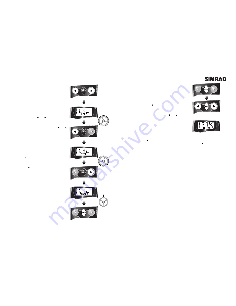
Fig 6.5 - Rate of turn too slow

6.5  Seatrial / Compass Calibration

Before using the AP14, the compass must be calibrated
to compensate for any magnetic deviation caused by fer-
rous or magnetic objects surrounding it on the boat, such
as cockpit speakers etc.

1. With the boat motoring along slowly (2-3 knots) in
calm conditions press the 

key a number of times (or

manually steer) to induce a slow clockwise rotation of the
boat (approx 3º/sec).

2. Press and hold 

Gain

, followed by the  

and 

keys

simultaneously to enter Auto Compass Calibration Mode
(Fig 6.4) The  display shows the heading, and the bottom
line will show CAL. 

3. Allow the boat to turn through a minimum of 1

1

4

turns

(450º) in approximately 2 

1

2

minutes, during which time

the fluxgate compass will automatically calibrate itself.  

4. If the rate of turn is too high, the display will flash arrows pointing to Port indicating decrease the
angle of turn - press 

.  If the rate or turn or boat speed is too slow the display will flash arrows

pointing to Starboard indicating increase the angle of turn (Fig 6.5) - press 

.

• It is recommended that the calibration is restarted if the Port arrows are shown more than twice.

A sequence of 4 beeps means that the calibration has been successful, and the AP14 will return to
Standby Mode.

• If after about four minutes the compass has not calibrated, an alarm will sound.  Repeat the above
procedure, following the directions carefully.  If the compass will still not calibrate then it is usual-
ly because the deviation being detected is too great, which may be due to the compass being too
close to a metallic or magnetic object (minimum safe distance - 1m [3 Ft]).  Move the compass to a
position as close to the ideal centreline location as possible, but away from speakers, metallic super-
structure etc.  Repeat the above procedure.

• This should only need to be done once when the autopilot is first commissioned, unless the com-
pass is changed, repaired, relocated or if any metallic objects have been installed or removed near
to the compass since it was calibrated.  In the interests of accurate performance, always bear in
mind the location of the compass when installing any metallic objects on the boat.  If in any doubt,
recalibrate the compass as shown above.

After calibrating the compass perform the following procedure -

1.  Hold the course steady for 5-10 seconds.
2.  Press 

Auto

to engage the autopilot and lock onto the heading - in calm conditions a constant

heading should be held.
3.  Alter course to Port and Starboard - the course change should be smooth without any sign of
overshooting.
4.  Look back at the wake of the boat to get an indication of the steering performance over a dis-
tance of at least 3km (2 Miles).  If there is any evidence of snaking or “S-ing”, try decreasing the
Gain setting (see section 3.1).
5.  If a GPS  is connected , the Nav Mode function should be tested over a longer distance.

Fig 6.4 - Auto Compass Calibration

POWER

ON

Fig 6.3 - Setting rudder limits

6.4  Setting Rudder Limits (AP14H only)

This two-stage procedure is used to -

• Define the maximum limits of the SLF12 pushrod stroke.

• Define the endstop and midstroke position of the rudder.

This data is permanently stored, so it will only be neces-
sary to repeat this procedure if the SCP12 is replaced or
the SLF12 is replaced/repositioned.

1. Turn the power to the pilot off at the breaker (or
switch).  Press and hold the 

and 

keys while switch-

ing the power on.

2. The display will show CAL and PORT (Fig 6.3).  If this
display is not shown, repeat step 1, holding the 

and 

buttons down firmly.

3. Disconnect the SLF12 rod from the ram and pull it fully
from the feedback body (the rod is not physically
attached to the SLF12 and can be removed easily).

4. Slide the rod all the way into the feedback body as far
as it will go, then reattach the rod to the rudder.  This sets
the maximum limits of the SLF12

5. Turn the helm hard over to Port, then back it off 

1

8

th of

a turn.  Push the 

key once, and the controller will beep,

showing STBD on the display.

6. Turn the wheel hard over to Starboard, then back it off

1

8

th of a turn.  Push 

once - the controller will beep and

show CENTRE on the display.

7. Turn the helm to the midships position and press

Gain

.  The pump will drive the rudder briefly to test

the limits entered.  If the rudder limits are accepted, the
controller will beep four times and the display will show
OKAY, otherwise it will sound a continuous alarm and
show FAIL, meaning that the calibration has failed -
repeat the above steps carefully.

• If the calibration still fails, this may indicate that the
hard over rudder position is beyond the sensing range of
the SLF12 or the system has not been bled properly and
the pump is airlocked.  Try repositioning the SLF12 so
that the stroke is within the defined parameters (see sec-
tion 4.3), bleed the system if necessary and repeat the
above procedure.

Note that the pilot will not enter Auto mode until the
rudder limits have been set.

Содержание AP14

Страница 1: ...Manual Simrad AP14 Autopilot ...

Страница 2: ... Mode 2 5 Set Key 2 6 Dodge 2 7 Backlighting 2 8 Alarms 2 8 1 Off Course Alarm 2 9 Default Boat Speed 2 10 Adjusting Dodge Angle 3 Parameter Adjustment 3 1 Rudder Movement Gain 3 2 Seastate 3 3 Autotrim 4 Installation AP14H Hydraulic Drive 4 1 Pump Installation SRP12 4 2 Bleeding The Steering System 4 2 1 Two or Three Line Systems 4 2 2 Pressurised Systems 4 3 Linear Feedback Unit SLF12 4 4 Fittin...

Страница 3: ...ccurate and dependable steering in varying sea conditions with minimal current consumption The AP14 a state of the art autopilot system with many advanced features is simple to operate and occupies little space on the dash The keypad accesses all functions and pilot status is indicated clear ly in the backlit LCD display To ensure the best results from your autopilot it is essential that the unit ...

Страница 4: ...Mode The AP14 has an inbuilt interface which allows it to be connected to NMEA0183 compatible equipment such as GPS LORAN Chart Plotters etc Once connected the AP14 can steer using data from this source in addition to the compass allowing a highly accu rate course to waypoint To enter Nav Mode the pilot must be in Auto Mode and receiving waypoint or route data from the navigational receiver Press ...

Страница 5: ...o toggle the alarm on and off press and hold the Alarm FIg 2 8 Dodging to Starboard Press hold Fig 2 9 Selecting backlighting level Page 8 key Fig 2 10 The alarm icon will be displayed while the alarm is on If the off course alarm sounds press Alarm to acknowledge and disable the alarm The off course limit can be set from 10 60º Press Set see section 2 5 until ALARM appears at the bottom of the di...

Страница 6: ... take a minute or so to fully compensate after a major course change Fig 3 3 Seastate deadband Average Course Fig 3 5 Autotrim principle COURSE HELD WIND TIDE Autotrim applied C o u r s e W i t h o u t A u t o t r i m Page 10 Page 11 3 Parameter Adjustment The AP14 uses highly advanced steering soft ware which constantly assesses how the boat is being affected by the sea conditions By adjust ing i...

Страница 7: ...of the cylinder unbalanced rams have the rod emerging from one end only Fig 4 1 Volume 3 142 x S R2 r2 S Stroke length R Cylinder bore radius r Push rod radius If S R and r are in inches the volume will be in cubic inches in3 If they are in centimetres then the volume will be in cubic centimetres cc An ideal location for the pump is in a gas inflammable vapour free area where it will not be immers...

Страница 8: ... not important which way round the pump outlet connections A B are connected to the steer ing lines as the pilot automatically sets the correct polarity when the unit is configured 4 2 Bleeding The Steering System The hydraulic system should be bled according to the manufacturer s instructions Make sure the cor rect oil is used to fill the system If there are no manufacturer s instructions availab...

Страница 9: ...uence FLYBRIDGE 1 Helm CABIN 2 Second Helm ENGINE BAY 3 SRP12 Page 16 7 Turn the helm clockwise until the ram is fully extended 8 Open the bleed valve on the ram cylinder nearest to the extended ram If there are no bleed valves fitted to the cylinder loosen the nut connecting the hydraulic hose to the cylin der to allow the air to escape Do not com pletely undo the bleed valve or nut 9 Holding the...

Страница 10: ... Unit SLF12 measures the rudder position and can be installed on most types of boat including I O or Outboard dri ves It is important that the SLF12 is properly installed with the maximum possible stroke minimum 150mm 6 0 in or it will not give an accurate reading The SLF12 is mounted onto the hydraulic ram cylinder using two mounting saddles Fig 4 11 Make sure that the maximum stroke of the hydra...

Страница 11: ...e 20 Fig 4 14 Connecting control unit Length of Cable Run Under 5M 16 6Ft 5 10M 33 3Ft Cross Section Area 2 5mm2 4mm2 Conductor Type 50 0 25 56 0 3 AWG 13 12 Fig 4 17 Cable selection table Fig 4 16 Mounting Course Computer 4 6 Fitting Course Computer SCP12 Locate the course computer in a moisture heat and vibration free area somewhere between the boat s power source and the pump to minimise power ...

Страница 12: ...ecting the AP14 to the power supply always check that the pilot and the receiver are not connected to a different battery bank This is to avoid a possible voltage drop between the interfaced equipment which would render the equipment inoperative The receiver must be running an active route or waypoint for the Nav Mode function to operate While any NMEA0183 compatible receivers should interface wit...

Страница 13: ...to the boat the fol lowing basic requirements must be met 1 The boat must have at least one single cable steering helm Dual cable systems which are for high performance boats or boats over 11m 35 Ft cannot be adapted for the AP14R However the AP14R can be fitted to boats with two steering positions providing that one has a single cable helm 2 There must be a minimum of 250mm 10 0 in clearance behi...

Страница 14: ...nnected Fig 5 5 Fit take up tube to the exit port and replace retaining bolt Page 26 the drive unit and wind it in by turning the steering shaft The cable should wind into the drive unit and emerge through the exit port into the take up tube Fig 5 6 Push the cable outer retainer into the entry port and refit the retain ing bolt to hold it in place Position the drive unit behind the dashboard and b...

Страница 15: ...objects such as stereo speakers heating units etc If the boat has a metal hull this includes fer rocement the compass must be mounted above decks on a mast or pole between one and two metres 3 to 7 feet above deck When mounting make sure that the compass is the right way up and is level The compass unit can be screwed to a vertical bulkhead using the two No 6 x 3 4in self tapping screws provided I...

Страница 16: ...ting the AP14 to the power supply always check that the pilot and the receiver are not connected to a different battery bank This is to avoid a possible voltage drop between the interfaced equipment which would render the equipment inoperative The receiver must be running an active route or waypoint for the Nav Mode function to operate While any NMEA0183 compatible receivers should interface with ...

Страница 17: ...ent carrying cables or other magnetic electronic equipment to avoid deviation 3 Has the compass been mounted as near as possible to the centrepoint of the boat to min imise heel angle HYDRAULIC PUMP AP14H ONLY 1 Have the correct fittings been used 2 Has return line R been fitted from the pilot pump 3 Are check valves fitted if needed 4 Has the system been correctly bled of air 5 Is the tubing to t...

Страница 18: ...uto to engage the autopilot and lock onto the heading in calm conditions a constant heading should be held 3 Alter course to Port and Starboard the course change should be smooth without any sign of overshooting 4 Look back at the wake of the boat to get an indication of the steering performance over a dis tance of at least 3km 2 Miles If there is any evidence of snaking or S ing try decreasing th...

Страница 19: ...Low Gain AP14H only AP14R only Page 36 Page 37 7 Appendix 7 1 Advice On Operation When making course changes be aware of the effect of a large course change on the boat espe cially when travelling at high speed the AP14 will respond very quickly to any instructions so it is advisable to reduce speed before changing course This should particularly be remembered when approaching a waypoint in Nav Mo...

Страница 20: ...der the black cover of the SRD12 Drive Unit can be used to identify the potential source of the problem Flashes Diagnosis Fault Location 5 Control unit not connected SHC14 6 No compass data received SHS12 7 No compass controls detected SHC14 SHS12 SRD12 8 Compass calibration failed SRD12 Page 38 7 5 Optional Accessories The following optional accessories for the AP14H and AP14R are available from ...

Страница 21: ...cally Linear Thrust 175kg 385 lbs Max Torque 19 5Nm 170 lb in Speed 15 rpm Page 40 25 mm 1 0 in 65 mm 2 56 in 155 mm 6 33 in 7 7 Service Warranty This unit is guaranteed for 2 years from date of retail sale If it is necessary to have the unit repaired return it carriage prepaid to the agent in the country of purchase with a copy of the receipted invoice showing the date of purchase Where possible ...

Страница 22: ......

Страница 23: ...d Navico Star Lane Margate Kent CT9 4NP United Kingdom Telephone 44 0 1843 290290 Telefax 44 0 1843 290471 E Mail sales simrad navico co uk W O R L D W I D E M A N U F A C T U R E R O F M A R I N E E L E C T R O N I C S ...

Отзывы: