background image

AIS Class B Transceiver

58

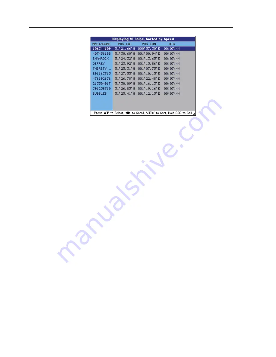
At the top just under the title bar are the Data Headings these are:

MMSI/NAME
COG
SOG
DISTANCE
CPA
TCPA
POS LAT
POS LON
UTC
HDG
ROT
CALLSIGN
IMO No
TYPE
DEST
ETA

Each consecutive line below the headings holds the voyage static data for 
a vessel within VHF range. Because this information does not fit on the 
screen, use the 

◄►

 keys to scroll across the page, and use the 

▲▼

 to 

scroll down the page.

 6.11.1  Changing the Sort Order

To change the display order in which the vessels are sorted, press the 
VIEW key, this will cycle through the following sort order: 


Fig.6.8 – Text Mode

Содержание AI50

Страница 1: ...MANUAL Simrad AI50 Class B Transceiver 988 0168 001 May07 English...

Страница 2: ......

Страница 3: ...MANUAL Simrad AI50 Class B Transceiver 988 0168 002 Iss 2 0 English...

Страница 4: ...thout notice as part of our policy of continuous development and improvement No part of this publication may be reproduced stored in a retrieval system or transmitted in any form electronic or otherwi...

Страница 5: ...ed 16 3 KEYPAD OVERVIEW 3 1 Layout 17 3 2 PWR Lights key Powering on and off 17 3 3 Navigation Keys 18 3 3 1 Display Mode 18 3 3 2 Menu Mode 18 3 3 3 Data Entry Mode 18 3 4 Zoom Keys 18 3 5 ENTER MENU...

Страница 6: ...urites List 33 5 4 1 Add an Entry 33 5 4 2 Edit an Entry 34 5 4 3 Delete an Entry 35 5 5 Alarm Setup 35 5 5 1 Collision Alarm 36 5 5 1 1 CPA TCPA 36 5 5 1 2 Guard Zone 37 5 5 2 Lost Vessel Alarm 38 5...

Страница 7: ...er Vessel Full list 56 6 8 4 Other Vessel Minimal list 56 6 9 General Rules for Vessel Information 57 6 10 Making a DSC Call in map mode 57 6 11 Text Mode 58 6 11 1 Changing the Sort Order 59 6 12 Mak...

Страница 8: ...ass B Transceiver VIII 8 APPENDIX 8 1 Maintenance 71 8 2 Troubleshooting 71 8 3 Accessories 72 8 4 Product Specifications 72 8 5 Dimensions 74 8 6 Service and Warranty 74 8 7 Declaration of Conformity...

Страница 9: ...arly equipped vessels within VHF range of each other to time share the same radio channel without interference This enables the automatic exchange of static information like MMSI Maritime Mobile Servi...

Страница 10: ...position of a vessel on the screen is the position of the most recent transmission and may not be the current position 1 2 About this manual The manual combines operating and installation information...

Страница 11: ...ry simple to install however the performance of the equipment is directly affected by the quality of the installation Please read these instructions carefully before attempting installation If in any...

Страница 12: ...op left and bottom right position 2 3 Bracket Mounting Using the supplied bracket as a template hold it against the surface it is going to be mounted on With a marker pen make a mark through the centr...

Страница 13: ...accessible to any personnel on board If this distance is achieved by vertical separation the antenna must be at least 5m 16 5ft above deck This guideline applies only to antennas not exceeding 3dBi ga...

Страница 14: ...tors be used Incorrectly rated cabling and connectors could result in power not reaching the antenna but also power could be reflected back into the AI50 unit damaging it in the process The quality of...

Страница 15: ...and has four wires For connection data refer to the following table Fig 2 4 Signal Colour Comment Out ve Orange Out ve Blue In ve Yellow Not Used In ve Green Not Used 0v Screen 2 7 SimNet Cable The A...

Страница 16: ...g screws and carefully remove the cover to reveal the SD card slot With the SD card contact side down place under the shroud and slide firmly into place making sure the card is sitting squarely and no...

Страница 17: ...t 3 2 PWR Lights key Powering on and off To turn the AI50 on press the PWR key Note When turning your AI50 on for the first time you will be directed to configure it for full use If this is declined t...

Страница 18: ...eturns you to the previous menu or mode Press and hold the key returns you to the Display Mode 3 3 3 Data Entry Mode During data entry the keys are used to highlight characters and numbers before usin...

Страница 19: ...ion to the centre of the display or the offset position if activated Press and holding the HOME DSC key initiates a DSC call to a highlighted vessel via an installed compatible SimNet VHF radio 3 9 VI...

Страница 20: ......

Страница 21: ...nd in windows displaying serious alarms it will be Red Information area The middle portion of the window will show the information menu or graphic relevant to the title displayed and will be grey Inst...

Страница 22: ...The default value is Yes as shown in Fig 4 3 If you wish to configure your AI50 now press MENU to continue go to section 4 3 1 Use the keys to change the value to No then press MENU to confirm If you...

Страница 23: ...ore detailed procedure is explained from section 4 3 1 onwards All values selected during this procedure will be automatically stored in the AI50 memory once completed WARNING All data entered during...

Страница 24: ...r and press the MENU to select it Continue to enter the rest of your number until complete Once you are sure that your MMSI number is correct highlight OK and press the MENU key Note OK will only func...

Страница 25: ...CEL button and press MENU A warning will be shown in the display Fig 4 9 Press the key and the display will revert back to the Configuration Request window Fig 4 3 Once the MMSI number has been entere...

Страница 26: ...to the systems memory 4 3 3 Vessel Dimensions GPS Reference Using the keys highlight Vessel Dimensions GPS Reference and press MENU or to select it A window opens as shown in Fig 4 12 All numeric entr...

Страница 27: ...and pressing the MENU key until the cursor is on the error position Now using the keys highlight the correct number and press the MENU to select it Once you entry is complete highlight OK and press ME...

Страница 28: ...bar Enter your vessel s name using the same method of entry as described during MMSI entry When complete highlight the OK button and press MENU to store it in the system memory Once the Vessel Name ha...

Страница 29: ...the Main menu select Display Mode and press MENU or A sub menu opens displaying the various options and their current status as shown in Fig 5 2 5 2 1 Coastline Detail This option allows you to toggle...

Страница 30: ...ll not be ticked To toggle this option on off highlight it and press MENU or and a tick will appear in the box When set to on your vessel is no longer maintained at the centre of the display and will...

Страница 31: ...no compass is connected to the system this mode will automatically appear as COG Up 5 2 4 Show Range Rings This option allows you to toggle the range rings on and off The default value is off and no...

Страница 32: ...t value in Use the keys to adjust the Keypad Brightness to a suitable level between 0 100 then press MENU or to store it Press to exit and return to the previous menu 5 3 3 Keypad Colour This option a...

Страница 33: ...so that you receive an alert when a vessel on your list comes within VHF range To set the alarm refer to section 5 5 3 There are two methods for adding vessels to your list 5 4 1 Add an Entry Method...

Страница 34: ...MMSI can be changed edited or deleted once entered If an entry is inserted without the name the next time that vessel is in range the name will be inserted automatically If a name already exists in th...

Страница 35: ...ite in the list Using the keys highlight the item you wish to delete and press MENU or The window shows three choices MMSI Vessel Name and DELETE Highlight DELETE and press MENU or 5 5 Alarm Setup Thi...

Страница 36: ...ge to show the activation status and values The default is Not Active Fig 5 11 5 5 1 1 CPA TCPA When you activate the CPA TCPA Alarm from within the Alarm Setup Menu the CPA TCPA will be calculated fo...

Страница 37: ...t an appropriate one 30ft 8 1nm or equivalent in selected units then press MENU or to accept it The cursor returns to highlight CPA Value Press to exit and return to the previous menu To change TCPA V...

Страница 38: ...or key A tick will appear in the box to indicate the alarm is now active GZ Radius To change GZ Radius use keys to highlight it then press MENU or to select it The value field is now highlighted Use...

Страница 39: ...Vessel Persistence When a vessel has been lost from AI50 reception its icon will change to a vessel icon with a strike through it Refer to section 6 2 Lost vessel persistence is the user assignable ti...

Страница 40: ...asure Set Local Time Ship Configuration Key Beeps Set Language Data Logging Transmit Enable Reset Options 5 6 1 Units of Measure This section allows you to change the units of distance and speed The o...

Страница 41: ...13 to 13 hours to the appropriate offset and press MENU or to select it Press to exit and return to the previous menu Note This will only affect the time being displayed in the own vessel information...

Страница 42: ...and return to the previous menu 5 6 5 Set Language This section allows you to change the operating language of your AI50 From the System Setup menu select Set Language and press MENU or the display c...

Страница 43: ...is highlighted Using the keys cycle through the predefined names AISLOG1 to AISLOG10 then press MENU or to select one Highlight Enable Logging and press MENU or A tick will appear in the box and the f...

Страница 44: ...not delete any of the data stored on it 5 6 6 3 Playback Log To playback a data log on your AI50 first you have to select the correct data file name for the voyage you wish to replay From the System...

Страница 45: ...eturn to the previous menu 5 6 8 Reset Options Selecting this option will reset all system variables back to their factory default settings except for the ship s configuration From the System Setup me...

Страница 46: ...be able to supply magnetic compass heading From the System Setup menu select SimNet NMEA2000 highlight Data Source and press MENU or The Data Source window will open with the Heading Highlighted Pres...

Страница 47: ...u 5 7 2 2 System Instance A SimNet system can have a maximum of 50 devices or Nodes attached to it If a large vessel has a requirement for more than 50 nodes then a multiple network system is required...

Страница 48: ...Enable and press MENU or to select it Press the MENU or key again to toggle the option On Off Press to exit and return to the previous menu 5 7 4 DSC Radio Select If a compatible DCS radio is installe...

Страница 49: ...ntifier Software version and Ship Configuration information From the Main menu select Product Info and press MENU or A window opens showing the first screen of information press the key to display the...

Страница 50: ......

Страница 51: ...ying one of these icons goes into an alarm state then the icon will turn red 6 3 Range Rings Range Info The Range rings consist of three concentric circles situated around the centre point of the disp...

Страница 52: ...reen to display any of the 12 ranges they are Total Range Across display No Range Showing own between rings Full display vessel info bar 1 0 01nm 0 08nm 0 06nm 2 0 02nm 0 16nm 0 12nm 3 0 05nm 0 4nm 0...

Страница 53: ...sel s icon North Up The top of the display lines up with True North HDG Up The top of the display lines up with the vessels True Heading COG Up The top of the display lines up with the vessels COG Tru...

Страница 54: ...automatically times out after approximately 30 seconds of inactivity A single press of any cursor keys will move it by 1 pixel in the direction of that key Press and holding the cursor key will allow...

Страница 55: ...Info Reduced list Using the keys place the cursor on the selected vessel a highlighted box will appear Press the INFO key once the display changes to show you a summary of that vessel s information F...

Страница 56: ...the information relating to that vessel Fig 6 6 To enter this vessel into your Favourites List press MENU or To initiate a call to this vessel using a suitable DSC VHF Radio If attached press and hol...

Страница 57: ...ating DSC Call window opens showing the MMSI number and name of the vessel you intend to call If this is correct and you wish to continue press MENU or to send the call The Routine DSC Call window ope...

Страница 58: ...nsecutive line below the headings holds the voyage static data for a vessel within VHF range Because this information does not fit on the screen use the keys to scroll across the page and use the to s...

Страница 59: ...once That icon will turn Bold and tracking will start immediately although a trail may not be noticeable until the vessel has moved sufficiently Fig 6 9 Multiple vessels can be tracked by selecting t...

Страница 60: ...See section 5 5 2 6 15 Clearing Down All Trails To clear all existing vessel trails including your own vessels press and hold TRACK CLR TRK for 2 seconds All vessels will return to their non bold sta...

Страница 61: ...is the highest priority alarm which require immediate action This alarm status if not acted upon with great urgency could result in loss or serious damage to your vessel and or loss of life Level 2 h...

Страница 62: ...user as described in section 5 5 1 1 WARNING It is the responsibility of the user to determine how close another vessel may pass without being dangerous and how quickly the user can react to manoeuvr...

Страница 63: ...on 5 5 2 has been set by the user or not If a vessel activates a CPA TCPA or Guard Zone alarm and the AIS transmissions from that vessel are lost regardless of what screen the AI50 is in an audible al...

Страница 64: ...ill sound regardless of what screen the AI50 is in and a Guard Zone Collision Warning window will be displayed Fig 7 3 To confirm and clear this alarm press the MENU key The icon of the vessel which c...

Страница 65: ...current display The icon of the vessel which caused the alarm to activate will change to a Lost Vessel icon refer to section 6 2 If the text display is active the text line for that vessel s data will...

Страница 66: ...p View Point mode is selected it will be cancelled and the display View Point will change to COG Up If the original compass unit returns to the network this will automatically be re selected and a mes...

Страница 67: ...Alarms 67 To confirm and clear this alarm press this will close the window and return you to current display...

Страница 68: ......

Страница 69: ...it will not switch on Faulty connector to power Fuse has blown Check power connection Replace fuse and check power supply No picture on display Unit not powered up Light level set too low Press PWR ke...

Страница 70: ...ransmit power 2Watt Type Approval IEC62287 1 GPS Receiver Receiver type Integral 16 channel receiver EMC IEC60945 Power Voltage 10 8 15 6VDC Current 1A SimNet NMEA2000 Network load 1 Backlighting Keyp...

Страница 71: ...129793 UTC and Date Report 129794 Class A Static and Voyage Related Data 129795 Addressed Binary Message 129796 Acknowledge 129797 Binary Broadcast Message 129798 SAR Aircraft Position Report 129800...

Страница 72: ...If it is necessary to have a unit repaired please contact your local authorized dealer For worldwide warranty details and a list of authorised Simrad agents please refer to the Warranty Card supplied...

Страница 73: ...levanta best mmelser som framg r av direktiv 1999 5 EG Danish Undertegnede Simrad Limited Margate erkl rer herved at f lgende udstyr AI50 overholder de v sentlige krav og vrige relevante krav i direkt...

Страница 74: ......

Отзывы: