

Anywhere Virtual Accessory Switch (4-Rocker)
Model US2-V04
Simply Automated, Incorporated
6108 Avenida Encinas, Suite B, Carlsbad, CA 92011 USA
or
800-630-9234
452-0052-4001 Rev. B Revised: March 31, 2016
Table 1
:
Power per Dimmer
Number of US1/US2 Switches in J-box
1
2
3+
Number
of J-box
Gangs
1
600W
--
--
2
800W
500W
--
3+
900W
700W
500W
2.
Disconnect power at the circuit breaker for the switch circuit. Utilize
the power ‘disconnect’ to prevent damage if wiring hot (see below).
3.
Remove the existing wall switch. Disconnect the wires to the switch.
4.
If a color/rocker change kit will be used to change out the faceplate,
see “INSTALLING/CHANGING FACEPLATES” section for details.
5.
At the switch location use a wire nut to connect all white (Neutral)
wires together. Make sure the connection is tight and strong to
ensure good communication between switches and accessories.
6.
At the switch location use a wire nut to connect the brown (load
output) wire of the switch to the black wire of the load/fixture to be
controlled. If the switch does not need to control a local load, then
cap the unused brown load wire with a wire nut.
7.
At the switch location use a wire nut to connect the black (Line) wire
of the switch to the black (Line) power wire. Make sure the
connection is tight and strong to ensure good communication
between switches and accessories.
8.
Mount the switch inside their respective J-box using captive screws.
DO NOT OVER TIGHTEN THE SCREWS.
9.
Reconnect power at the circuit breakers.
10. Top-Rocker: Press and release top of the top-rocker to turn on switch
and any other installed Anywhere accessories that are set on
channel #2. Press and release bottom of top-rocker to turn off switch
and any other installed Anywhere accessories on channel #2.
11. Other-Rockers (see wiring diagram): Press and release top of the
rocker to turn on installed Anywhere accessories that are set on
channel # 1, 3, or 4. Press and release bottom of bottom-rocker to
turn off other installed Anywhere accessories on channel # 1, 3 or 4.
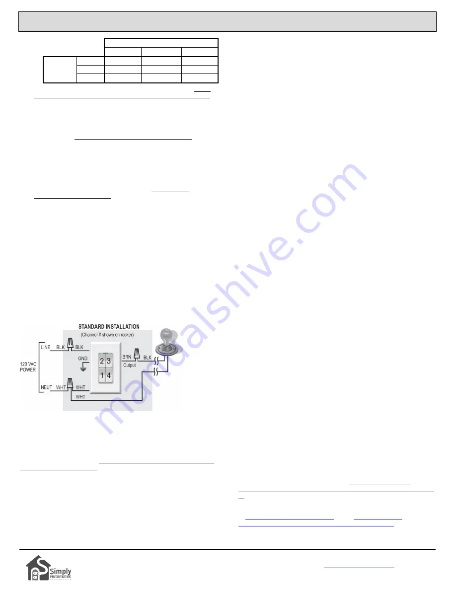
WIRING DIAGRAM
Anywhere switch requires a hot (line) and neutral connection. The brown
load wire connects to the lighting circuit (switch leg). If no lighting circuit
needs to be connected at the switch then cap brown wire with a wire nut.
POWER DISCONNECTION
To disconnect power to the switch and connected lamp fixture, depress
the top of the rocker switch, grab the underside of the clear plastic
indicator tab (light pipe) with your fingernail, and pull the tab out about 0.2”
until it stays in place. The LED indicator will extinguish showing that
power is now disconnected. To reconnect power, simply push the tab
back into its normal position. Utilize the ‘disconnect’ to prevent damage if
the switch must be wired hot.
CHANGING CHANNELS
If separate lighting ‘zones’, or ‘sets’ of Anywhere Remote Lighting
Controls will be used on the properties’ power service, then the separate
‘set’ of switches and accessories will need to be configured for a channel
other than #2 (US2-V0 local load). The US2-V04 rocker channels are
fixed, they cannot be changed. However, there are four (4) available
channels that can be used by other Anywhere devices (US1-V0, UMA-V0,
UFR-V0 and URD-V0) and changing them is easy. Refer to the User
Guide of the specific Anywhere device to change its channel.
FACTORY DEFAULT SETTINGS
To restore the switch to the original factory default settings (e.g.
responding to channel #2 only), tap the rocker 5 times quickly. The LED
will flash green. Then tap the rocker 10 times quickly. The LED will flash
blue. Tap the rocker 2 times quickly and the LED will stop flashing. At this
point the switch is reset.
INSTALLING/CHANGING FACEPLATES
Anywhere Switches are designed with removable actuator faceplates,
making it possible to change color in the field without disconnecting the
switch from the wall.
To remove the faceplate assembly to change color, do the
following:
1.
If installed in a junction box, remove the wall plate framing the switch.
2.
Using the thumb and index finger, press the top two side-prongs of
the rocker faceplate assembly inward so that they unlatch from the
switch body. This will release the top of the rocker assembly.
3.
Press the two lower side-prongs inward, and pull the faceplate
assembly away and slightly downward from the switch body, moving
it away from the clear plastic light pipe.
4.
Once the faceplate is removed, follow steps 1-4 below for
instructions on installing a new rocker faceplate assembly.
To install a faceplate assembly, do the following:
1.
Hold the actuator faceplate assembly so that clear plastic light pipe
(LED) on the switch fits nicely into the recess on the top of the
faceplate.
2.
Align the four prongs on the side of the faceplate assembly with the
four slots on the switch body.
3.
While squeezing the prongs on both sides, press the faceplate
straight onto the switch body. Ensure that all four prongs are fully
inserted and latched into the switch body. If all four prongs are not
fully latched, the rocker plungers may not function properly.
4.
Exercise rocker several times to ensure proper seating and
operation. If the rocker doesn’t operate properly, remove and re-
install the faceplate to check proper seating and operation.
TROUBLE SHOOTING
Simply Automated’s Powerline technology is extremely robust. Using large
low frequency pulses in a patented pulse position modulation protocol,
they can overcome power line noise and capacitive attenuation in most
(98%) applications. In the event that the switch and accessories are set
for the same channel, but are not communicating (i.e. turning each other
on/off) or controlling the local light/load circuit(s), here are steps to
diagnose and resolve the issue:
1)
Are the LED indicators lit on both switches, indicating the switches
are powered? If not, make sure the Power Disconnect (LED light
pipe) is pressed in, check hot and neutral wire-nut connections and
circuit breaker state.
2)
Do both the switches’ LEDs change from blue to green when turning
from off to on? If not, check hot and neutral wire-nut connections
making sure the connection is tight and strong for good
communication. If yes, then check the brown load wire connection to
the fixtures’ switch leg, and if necessary the light fixture and bulb. A
volt meter or power indicator probe is helpful in confirming switch leg
power vs. bulb/fixture fault.
At this step one switch should be turning the lighting circuit on/off. Or if
each switch has a connected lighting circuit then each switch should be
able to control its own lighting circuit. If they are not controlling each other,
double check they are on the same channel (try resetting to factory default
as described above). If they still don’t control each other there would
appear to be a communication issue, and phase alignment (swap
breakers/wires so both switched are on the same phase, either phase A or
B) or installing a phase coupler (model ZPCI) may be necessary. For
addition trouble shooting assistance, please call or write Simply
Automated Technical Support at 800-630-9234 / 760-431-2100 (Ext. 138)
or
or see
automated.com/Anywhere_Virtual_3-way_Applications.php


