background image

34

Regular Maintenance

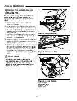
SERVICING THE MOWER BLADES

1. Remove mower from the tractor. See Mower

Installation & Removal.

2. Blades should be sharp and free of nicks and dents.

If not, sharpen blades as described in following steps.

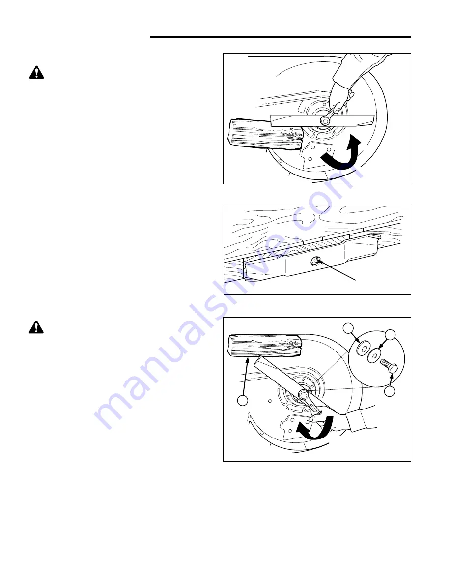
3. To remove blade for sharpening, use a wood block to

hold blade while removing the blade mounting cap-

screw (Figure 42).

4. Use a file to sharpen blade to fine edge. Remove all

nicks and dents in blade edge. If blade is severely

damaged, it should be replaced.

5. Balance the blade as shown in Figure 43. Center the

blade’s hole on a nail lubricated with a drop of oil. A

balanced blade will remain level.

6. Reinstall each blade with the tabs pointing up toward

deck as shown in Figure 44. Secure with a capscrew

(D, Figure 44), spring washer (C), and spline washer

(B).  Be certain the spline washer is aligned with the

shaft splines. Use a wood block to prevent blade

rotation and torque capscrews to 45-55 ft.lbs. (61-75

N.m.).

Figure 44. Installing The Blade
A. Wood Block
B. Spline Washer
C. Spring Washer
D. Capscrew

WARNING

For your personal safety, do not handle the sharp
mower blades with bare hands. Careless or
improper handling of blades may result in serious
injury.

WARNING

For your personal safety, blade mounting
capscrews must each be installed with a hex
washer and spring washer, then securely
tightened. Torque blade mounting capscrew to 
45-55 ft. lbs. (61-75 N.m.)

Figure 42. Removing the Blade

Figure 43. Balancing The Blade

Workbench

Nail

LOOSEN

A

D

C

B

TIGHTEN

Not 

for  

Reproduction

Содержание Legacy XL 2000 Series

Страница 1: ... XL 27HPD 4WD 3P 54 Mower 2690423 Legacy XL 27HPD 4WD 3P 60 Mower CE 2690310 Legacy XL 27HPD 2WD 54 Mower CE 2690382 Legacy XL 27HPD 4WD 3P CE 2690308 Legacy XL 27HPD 4WD 3P 54 Mower CE 2690309 Legacy XL 27HPD 4WD 3P 54 Mower CE 2690314 2027 27HP 4WD 60 Mower 2690315 2027 27HP 4WD 54 Mower Mfg No Description 2690364 2027 27HPLC 4WD 2690313 2027 27HPLC 4WD 60 Mower 2690365 2027 27HPLC 4WD 3P 269031...

Страница 2: ...N o t f o r R e p r o d u c t i o n ...

Страница 3: ...ving the Tractor 15 Mowing 15 Mowing in Reverse 15 Attachment Operation in Reverse 15 4 Wheel Drive Operation 15 Pushing the Tractor by Hand 16 Hydraulic System Functions 16 Optional 3 Point Hitch Operation 18 540 Rear PTO Operation 20 Mower Deck Removal Installation 22 Attaching a Trailer 24 Storage 24 12 Power Outlet 24 Regular Maintenance 25 Maintenance Schedule 25 Engine Maintenance 26 Clean D...

Страница 4: ... the product s features and controls and maintenance information is included to help you get the most out of your equipment investment Be sure to completely read the Safety Rules and Information found on the following pages Also completely read the Operation section Children Tragic accidents can occur with children Do not allow them anywhere near the area of operation Children are often attracted ...

Страница 5: ... it is equipped with an operator present safety system Do NOT attempt to alter or bypass the system See your dealer immediately if the system does not pass all the safety interlock system tests found in this manual Thrown Objects This unit has spinning mower blades These blades can pick up and throw debris that could seriously injure a bystander Be sure to clean up the area to be mowed BEFORE you ...

Страница 6: ...truction 22 Always wear substantial footwear and trousers Never operate when barefoot or wearing sandals 23 Before using always visually check that the blades and blade hardware are present intact and secure Replace worn or damaged parts 24 Disengage attachments before refueling removing an attachment making adjustments unless the adjustment can be made from the operator s posi tion 25 When the ma...

Страница 7: ...ays keep unit in gear especially when traveling down slopes Do not shift to neutral and coast down hill 6 Avoid starting stopping or turning on a slope If tires lose traction disengage the blade s and proceed slowly straight down the slope 7 Keep all movement on slopes slow and gradual Do not make sudden changes in speed or direction which could cause the machine to rollover 8 Use extra care while...

Страница 8: ...ps grip hoses firmly over the filter after installation 12 Do not use gasoline containing METHANOL gasohol containing more than 10 ETHANOL gasoline addi tives or white gas because engine fuel system dam age could result 13 If the fuel tank must be drained it should be drained outdoors 14 Replace faulty silencers mufflers 15 Maintain or replace safety and instruction labels as necessary 16 Use only...

Страница 9: ...tra copy of the identification tag in the manual S A M P L E S A M P L E North American CE Models CE Models Only CE IDENTIFICATION TAG MARKINGS A Manufacturer s Identification Number B Manufacturer s Serial Number C Power Rating in Kilowatts D Maximum Engine Speed in Rotations per Minute E Manufacturer s Address F Year of Manufacture G CE Compliance Logo H Mass of Unit in Kilograms I Sound Power i...

Страница 10: ...DRIVE ON IT ROTATING BLADES CUT OFF ARMS AND LEGS RMO System STOP MOWER WHEN CHILDREN ARE NEAR NO RIDERS THEY FALL OFF This product is equipped with the RMO system Refer to the operator s manual for a full explanation of the RMO system and for important safety messages DANGER AVOID SERIOUS INJURY OR DEATH READ OPERATOR S MANUAL S KNOW LOCATION AND FUNCTION OF ALL CONTROLS KEEP SAFETY DEVICES GUARD...

Страница 11: ...eat switch operation every fall and spring with the following tests Test 1 Engine should NOT crank if PTO switch is ON OR Brake pedal is NOT fully depressed parking brake OFF OR The cruise control lever is NOT in NEUTRAL Test 2 Engine SHOULD crank if PTO switch is OFF AND Brake pedal is fully depressed parking brake ON AND The cruise control lever is in NEUTRAL Test 3 Engine should SHUT OFF if Ope...

Страница 12: ...used to check the front axle oil level and to add oil to the axle See FRONT AXLE MAINTENANCE for oil level check and fill proce dures Transmission Oil Level Check Plug Transmission oil check plug dipstick is used to check transmission oil level and to add oil to the transmission See TRANSMISSION MAINTENANCE for oil level check and fill procedures CONTROL FUNCTIONS The information below briefly des...

Страница 13: ...tion with the engine stopped this drains the battery Brake Pedal Depressing the brake pedal applies the tractor brake Depressing the brake pedal will also return the cruise control lever to neutral 11 Features Controls Ground Speed Pedals The tractor s forward ground speed is controlled by the forward ground speed control pedal The tractor s reverse ground speed is controlled by the reverse ground...

Страница 14: ...hydraulic circuit is controlled by the forward and back ward movement of the attachment lift lever When the switch is in the forward position the attach ment lift control lever affects attachments connected to the two front left quick couplers When the switch is in the rear position the attachment lift control affects the tractor s hydraulic cylinder Power Outlet Select Models The power outlet is ...

Страница 15: ...he mid PTO is engaged D Hour Meter Clock Displays number of hours the unit has been operated E Cruise Control Light Indicates that the cruise control is engaged F Low Oil Pressure Light Indicates that the engine oil pressure is low If this indi cator lights shut the engine off immediately and contact your dealer G 4 Wheel Drive Light 4WD Models Only Indicates that 4 wheel drive is engaged H Fuel S...

Страница 16: ...emergency the engine can be stopped by simply turning the ignition switch to STOP Use this method only in emergency situations For nor mal engine shut down follow the procedure given in STOPPING THE TRACTOR GENERAL OPERATING SAFETY Be sure to read all information in the Safety and Operation sections before attempting to operate this unit Become familiar with all of the controls and how to stop the...

Страница 17: ...an operator chooses to mow in reverse the RMO sys tem can be used To use the Reverse Mowing Option RMO turn the RMO key after the PTO is engaged The L E D light will illuminate and the operator can then mow in reverse Each time the PTO is disengaged the RMO needs to be reactivated if desired The key should be removed to restrict access to the RMO feature ATTACHMENT OPERATION IN REVERSE If an opera...

Страница 18: ...t be in the REAR position Pulling the lever back raises the attachment lift A Figure A B 7 6 5 4 3 0 100 200 300 400 Implement Flow gpm Implement Flow 3600 RPM Pressure psi Figure 5 Hydraulic System Pressure Flow Figure 6 Inboard Hydraulics A Lift B Lower Figure 4 Transmission Release Lever Fuel Tank A Fuel Tank Cap B Transmission Release Lever B A PUSHING THE TRACTOR BY HAND 1 Disengage the PTO a...

Страница 19: ...sables the inboard hydraulic cylinder Moving the control lever to the left A Figure 7 angles the attachment left Moving the lever right B Figure 7 angles the attachment right Pulling the lever back raises the attachment lift A Figure 8 Pushing the lever forward to the first detent lowers the attachment lift B Figure 8 Pushing the lever for ward to the second detent locks the control in float posit...

Страница 20: ...hen using a rear mounted attachment Remove the front weights when the rear attachment is removed Figure 10 Attachment Weight Limit Figure 9 Attachment Weight Limit A B Figure 11 Hitch Rod Positions A Rod Storage B To Lock Lift In Raised Position Locking The Hitch The 3 point hitch can be locked in the raised position When a rear attachment is locked in the raised position the tractor s on board hy...

Страница 21: ... the hitch using a clevis pin F and safety clip E 2 Attach the sway arms A Figure 12 to the hitch assembly using clevis pins C and hair pin clips B The arms should angle out away from center 3 Attach the sway chains D Figure 13 to the back of the sway arms A E using 3 8 x 1 1 2 capscrews C and 3 8 locknuts Cross the chains and secure to front of the sway arms with clevis pins and hair pin clips B ...

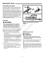
Страница 22: ...everal minutes before engaging the PTO 4 Set engine throttle to FULL 5 Place the PTO selector lever in the rear position A Figure 16 if only a rear attachment is being used If a mid and rear attachment are being used simultane ously place the lever in the mid position B If only a mid or front attachment is being used place the con trol in position C 6 Pull UP on the PTO switch to engage the PTO 7 ...

Страница 23: ...that require more than 18 HP or an input shaft speed other than 540 could result in poor performance shortened equipment life or equipment damage and will void the tractor warranty Improper use can also create an unsafe condition resulting in injury START UP AND STOPPING LOADS This PTO can be used with direct drive attachments that have small start up and stopping loads like tillers or mower decks...

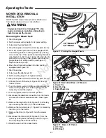
Страница 24: ...ift chains A Figure 19 from the tractor lift arms 12 Turn the ignition switch to RUN position and set the mower cutting height to its lowest setting it is not necessary to start the engine 13 Turn the ignition switch to the OFF position 14 Disconnect the electrical connection from the tractor and recap the tractor electrical socket See Figure 20 15 Remove the long hitch pin B Figure 21 and safety ...

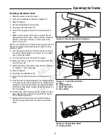
Страница 25: ...ount the hitch A Figure 21 to the deck using the long hitch pin B 11 Attach the hitch to the tractor using the two short pins C Figure 21 and safety clips 12 Start the engine 13 Fully raise the attachment lift 14 Shut off the engine and wait for all moving parts to stop 15 Pivot the two front gauge wheels from sliding position to mowing position by pushing down on the top of the spindle and pivoti...

Страница 26: ...be increased if it is removed put in a cool dry place and fully charged about once a month If the battery is left in the unit disconnect the nega tive cable Before starting the unit after it has been stored Check all fluid levels Check all maintenance items Perform all recommended checks and procedures found in the engine owner s manual Allow the engine to warm up for several minutes before use WA...

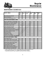
Страница 27: ...E ITEMS Check Tractor Mower for Loose Hardware Clean Debris Out of Engine Compartment Clean Engine Oil Cooler Air Cooled Clean Radiator Liquid Cooled Clean Transmission Oil Cooler Check Transmission Oil Level Change Transmission Oil Filter Check Front Transaxle Oil Level 4WD Only Check Mower Gear Box Oil Level Check Tire Pressure Clean Battery Cables Lubricate Tractor Mower Clean Deck Check Replac...

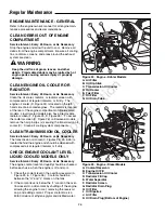
Страница 28: ...res 24 25 26 is located behind the engine and should be cleaned with compressed air at regular intervals or if dirty CHECK ENGINE COOLANT LEVEL LIQUID COOLED MODELS ONLY Service Interval Every 25 Hours or As Necessary The engine coolant level and quality should be checked before each use when the engine is off and cool 1 Check the coolant level in the overflow reservoir A Figure 25 I Figure 26 Coo...

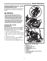
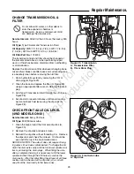
Страница 29: ...ttom LH Side of Engine I Coolant Reservoir J Hair Pin Clips D D J E F B I C C A G CHANGE FUEL FILTER GAS MODELS Service Interval Every 100 Hours or As Necessary Models with Kohler engines see E Figure 24 Models with Kawasaki engines see F Figure 26 If the filter is dirty or clogged replace as follows 1 Disconnect the negative battery cable 2 Place a container below the filter to catch spilled fuel...

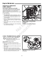
Страница 30: ...Service Interval Seasonally or as Needed The fuel filter assembly has a built in water separator that should be drained when the indicator light in the dashboard display turns on or once per season Replace the fuel filter element every 800 hours of opera tion or as required To drain the fuel filter 1 Turn the engine off set the parking brake remove the ignition key and wait for all moving parts to...

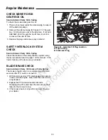
Страница 31: ... 29 Regular Maintenance Figure 30 Front Axle Lube A Dip Stick CHECK FRONT AXLE OIL LEVEL 4WD MODELS ONLY Service Interval Every 25 Hours Oil Type 80W 90 Gear Lube 1 Clean the area around the front axle dip stick A Figure 30 2 Remove the dip stick and wipe it clean 3 Reinsert the dip stick without threading it in Remove the dips stick and check the oil level Oil should be even with the top of the h...

Страница 32: ...anders 2 Engage the PTO and wait several seconds Disengage the PTO and check the amount of time it takes for the mower to stop 3 If the mower does not stop within five seconds see your dealer Figure 31 Gear Box Fill Plug Location A Top Fill Plug B Side Level Plug A B CHECK MOWER DECK GEAR BOX OIL Service Interval Every Fall Spring To check the mower deck gear box oil 1 Place a shop towel under the...

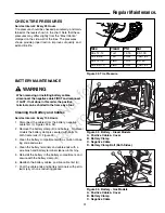
Страница 33: ...moving or installing battery cables disconnect the negative cable FIRST and reconnect it LAST If not done in this order the positive terminal can be shorted to the frame by a tool Figure 33 Battery Diesel Models A Positive Cable Cover B Battery Clamp C Negative Cable D Battery Clamp Bolt Both Sides A C D B Figure 34 Battery Gas Models A Positive Cable Cover B Battery Clamp C Negative Cable A C B F...

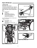
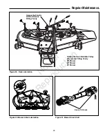
Страница 34: ...er linkage transmission idler assembly pivot rear axle shafts remove wheel hubs front axle where it contacts the frame all drive shaft universal joints mower belt tension bracket pivots Use grease fittings when present Automotive lithium grease is recommended Oil control linkage seat adjustment assembly brake linkage mower deck height adjustment linkage manual lift lever Figure 35 Lubricating the ...

Страница 35: ...od Grease Fitting Yearly Grease the Deck Belt Idler Pulley Arm Grease Fitting Yearly 48 Mower 60 Mower 54 Mower Figure 41 Mower Drive Shaft Figure 40 Mower Arbor Lubrication Figure 39 Deck Lubrication Every 10 Hours N o t f o r R e p r o d u c t i o n ...

Страница 36: ...tabs pointing up toward deck as shown in Figure 44 Secure with a capscrew D Figure 44 spring washer C and spline washer B Be certain the spline washer is aligned with the shaft splines Use a wood block to prevent blade rotation and torque capscrews to 45 55 ft lbs 61 75 N m Figure 44 Installing The Blade A Wood Block B Spline Washer C Spring Washer D Capscrew WARNING For your personal safety do no...

Страница 37: ...35 Regular Maintenance MAINTENANCE RECORDS N o t f o r R e p r o d u c t i o n ...

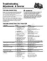
Страница 38: ...lty See your dealer 12 Spark plug s faulty fouled Clean and gap or replace or incorrectly gapped See engine manual 13 Water in fuel Drain fuel refill with fresh fuel Replace fuel filter 14 Gas is old or stale Drain fuel refill with fresh fuel Replace fuel filter Engine starts hard or runs poorly 1 Fuel mixture too rich Clean air filter Check choke adjustment 2 Spark plug s faulty fouled or Clean a...

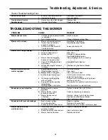
Страница 39: ... Mower Blades to arbors Engine stalls easily with 1 Engine speed too slow Set to full throttle mower engaged 2 Ground speed too fast Slow down 3 Mower choked with grass Clean out mower deck 4 Cutting height set too low Cut tall grass at maximum cutting height during first pass 5 Discharge chute jamming Cut grass with discharge pointing toward with cut grass previously cut area 6 Engine not up to o...

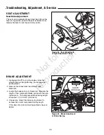
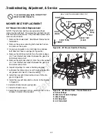
Страница 40: ...e spring length should be 3 1 2 to 3 3 4 8 9 9 5cm 4 If necessary adjust the brake spring locknut to achieve the correct compressed spring length If this does not correct a braking problem see your dealer Figure 45 Seat Adjustment A Seat Adjustment Lever A 3 5 3 75 8 9 9 5cm Figure 46 Brake Adjustment A Brake Spring A SEAT ADJUSTMENT Seat Slide Adjustment The seat can be adjusted forward and back ...

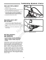
Страница 41: ...placement BATTERY CHARGING A dead battery or one too weak to start the engine may be the result of a defect in the charging system or other electrical component If there is any doubt about the cause of the problem see your dealer If you need to replace the battery follow the steps under Cleaning the Battery Cables in the Regular Maintenance Section To charge the battery follow the instructions pro...

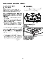
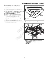
Страница 42: ...if scalping occurs at lower cutting heights due to uneven terrain Figure 49 Anti Scalping Rollers A Rollers B Mower Baffle A B Gauge Wheel Adjustment 54 Mower Only The mower gauge wheels can be placed in two positions depending on the height of cut When using higher cut ting heights set the wheels in the lower position When using lower cutting heights set the wheels in the upper position To adjust...

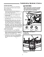
Страница 43: ... the outside tips of each blade and the ground If there is more than 1 8 3mm difference between the measurements on each side proceed to step 7 If the difference is 1 8 3mm or less proceed to Front To Back Leveling 7 See Figure 51 Loosen the outside nut A then turn the eccentric nut B to raise or lower the left side of the deck Repeat on the right side of the deck When the mower deck is level hold...

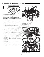
Страница 44: ...ve belt D from the arbor pulleys A Twist the belt and slide it between the gear box and mower deck shell 6 Inspect all pulleys for wear or bearing damage 7 Lubricate the idler arm pivots with multi purpose lithi um grease and check for free movement 8 Install the new right drive belt as shown in the dia gram in Figure 53 9 Install the new left drive belt as shown in the diagram in Figure 53 10 Ins...

Страница 45: ...ssembly tension spring B Figure 56 4 Remove the old drive belt D 5 Inspect all pulleys for wear or bearing damage 6 Lubricate the idler arm pivot with multi purpose lithi um grease and check for free movement 7 Install the new drive belt as shown in the diagram in Figure 55 8 Reinstall the belt covers Be sure the alignment notches are centered on the screws 9 Install the mower deck and run under n...

Страница 46: ...en the gear box and mower housing 7 Inspect all pulleys for wear or bearing damage 8 Lubricate the idler arm pivots with multi purpose lithi um grease and check for free movement 9 Install the new right drive belt as shown in the dia gram in Figure 57 10 Install the new left drive belt as shown in the diagram in Figure 57 11 Reinstall and tighten the gear box mounting screws A Figure 59 12 Install...

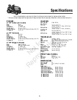
Страница 47: ...ressure 20 22 psi 1 38 1 52 bar TRANSAXLE Make Tuff Torq Kanzaki Type K92 Integrated Hydrostatic Pump Transaxle Hydraulic Fluid Type F Automatic Transmission Fluid Capacity 2WD 8 qt 7 6L 4WD 8 2 qt 7 8L 4WD 540 9 5 qt 9L Speeds Forward 0 9 0 mph 0 14 4 kph 3400 rpm Reverse 0 5 5 mph 0 8 8 kph Continuous Torque 1200 ft lbs 166 kg m Output Drawbar Rating 1111 lbs 504 kg Maximum Weight 1800 lbs 816 k...

Страница 48: ...included Technical manuals can be downloaded from www simplicitymfg com Snowthrower Cab Snowthrower Attachments Dozer Snow Blade Rear Wheel Weights Tire Chains Grass Catcher Dump Cart Gas Cans Loader R O P S Rotary Broom Rear Weight Carrier Front Weight Carrier Triple Bag Collector Turbo Collector Tiller Engine Oil Touch Up Paint Grease Gun Kit 8 oz Grease Tube Tire Sealant Degrimer Degreaser Gas ...

Страница 49: ...s requested the manufacturing date of the product will be used to determine warranty eligibility ABOUT YOUR WARRANTY We welcome warranty repair and apologize to you for being inconvenienced Warranty service is available only through servicing dealers authorized by Briggs Stratton or BSPPG LLC Most warranty repairs are handled routinely but sometimes requests for warranty service may not be appropr...

Страница 50: ...N o t f o r R e p r o d u c t i o n ...

Страница 51: ...N o t f o r R e p r o d u c t i o n ...

Страница 52: ...G INC PO Box 702 Milwaukee WI 53201 0702 www SimplicityMfg com PO Box 702 Milwaukee WI 53201 0702 AGCOLawn com Briggs Stratton Power Products Group LLC Copyright 2011 Briggs Stratton Corporation Milwaukee WI USA All Rights Reserved N o t f o r R e p r o d u c t i o n ...
Отзывы: