background image

18

A

C

C

C

B

B

C

A

B

B

C

C

E

D

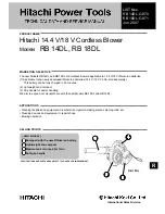
Figure 13.  Top Cover 
and Belt Cover
A. Screw, 1/4-20 x 5/8
B. Screw, #10-24 x 1/2
C. Screw, 1/4-14 x 3/4
D. Top Cover
E. Belt Cover

COVER REMOVAL AND
INSTALLATION

To access the drive system or the engine, the covers
must be removed as follows:

REMOVE THE TOP COVER

1. Remove the discharge chute. See “Chute Removal

and Installation”.

2. Remove the fuel cap.

3. Remove the screws (A, Figure 13) and nuts from the

front of the top cover (D).

4. Remove the screws (B) and nuts from the left and

right side of the top cover (D).

5. Remove the eight screws (C) on the left and right

side of the top cover (D).

6. Remove the five screws (C) from the back portion of

the control panel.

7. Carefully pull the rear of the top cover up and over

the gas tank.

8. Installation of top cover (D) is reverse of removal.

REMOVE THE BELT COVER

1. Remove the screws (B, Figure 13) and nuts that hold

the belt cover (E) to the auger housing.

2. If the top cover (D) has not been removed, then

remove the screws (C) that attach the belt cover to
the top cover.

3. Remove screw (C) that holds the belt cover (E) to the

top cover (D).

4. To remove, hold the bottom portion of the belt cover

(E) and pull down and out.

5. Installation of belt cover (E) is reverse of removal.

Troubleshooting & Service

Содержание 1695468

Страница 1: ...e immediately after the front cover The part number for this manual typically a 174_____ number is located on the front cover This file may contain several manual which differ only by their covers See...

Страница 2: ...THIS PAGE INTENTIONALLY BLANK FOR PLACEMENT ONLY DO NOT PRINT...

Страница 3: ...OPERATOR S MANUAL Single Stage Snowthrower 522E Models Mfg No Description 1695468 522E Snowthrower 1695514 522E Snowthrower CE 1742166 00 Rev 7 2008 TP 100 4961 00 SW S...

Страница 4: ......

Страница 5: ...vice Troubleshooting 17 Chute Removal and Installation 17 Cover Removal and Installation 18 Replacing the Drive Belt 19 Servicing the Spark Plug 20 Auger Drive Cable Adjustment 21 Appendices Specifica...

Страница 6: ...RING operation Safe operating techniques an explanation of the product s features and controls and maintenance information is included to help you get the most out of your equipment investment Be sure...

Страница 7: ...ow snow and ice Thrown debris could seriously injure a bystander ALWAYS direct the discharge chute away from bystanders and prop erty that could be damaged by flying debris Be sure to clean up the are...

Страница 8: ...st to outdoor temperatures before starting to clear snow 9 Always wear safety glasses or eye shields during operation or while performing an adjustment or repair to protect eye from foreign objects th...

Страница 9: ...valuate their ability to operate the unit safely enough to protect themselves and others from injury 23 DO NOT wear long scarves or loose clothing that could become entangled in moving parts 24 Snow c...

Страница 10: ...xxxxxxxxxx xxxxxxxxxxxxxxxxxxxxxxx xxxxxxxxxxxxxxxxxxxxxxx xxxdB kg xxx S A M P L E S A M P L E North American Models CE Models ENGINE REFERENCE DATA Model Description Name Number Unit MFG Number PROD...

Страница 11: ...ler Part No 725257MA North American Auger Danger Decal Part No 1740428MA North American Danger Warning Main Dash Decal International Symbols Part No 724267 North American Unclogging Chute Danger Decal...

Страница 12: ...lay the panels flat 5 Hold onto the lower handle and pull the snowthrower off the carton CAUTION DO NOT back over cables 6 Remove the packing material from the handle assembly ASSEMBLY PROCEDURE Snow...

Страница 13: ...ting add this oil to the engine 2 Remove the oil fill cap dipstick access panel A Figure 5 3 Remove the oil fill cap dipstick B Fill to the FULL mark on the oil fill cap dipstick Periodically check th...

Страница 14: ...tion of auger Deflector Controls B Chute Direction Control The Chute Direction Control B Figures 6 7 allows the discharge chute to be rotated to throw snow in the desired direction Snow may be thrown...

Страница 15: ...haft cycles the engine and generates the spark neces sary for starting the engine D Primer Button When pressed the Primer Button D provides initial fuel to help start a cold engine Normally pressing t...

Страница 16: ...erious injury do not put your hands into the auger housing or discharge chute If the auger stalls or chute becomes plugged use the following procedure to remove objects or clear the chute 1 Release th...

Страница 17: ...ulat ed automotive gasoline with a minimum of 85 octane along with a fuel stabilizer follow instructions on fuel stabilizer package DO NOT use leaded gasoline Controls Operation Figure 9 Add Check Eng...

Страница 18: ...To stop engine turn engine key to the OFF position Manual Recoil Starting Steps 1 Insert engine key in switch and turn key to the ON position 2 If engine is cold move choke control lever to the ON po...

Страница 19: ...to reduce the likelihood of parts freezing while machine is not is use If you will be storing the unit for the season see the STORAGE section for instructions on properly preparing the unit for long...

Страница 20: ...A few drops of oil should be placed on wheel hubs occasionally to keep wheels turning freely Apply oil to pivot points of auger control peri odically wiping off any excess oil A couple of drops of li...

Страница 21: ...arts hard or runs poorly 1 Fuel mixture too rich 1 Move choke to OFF position 2 Spark plug faulty fouled 2 Clean and gap or replace or gapped incorrectly 3 Water in fuel or old fuel 3 Drain tank Dispo...

Страница 22: ...p cover D 5 Remove the eight screws C on the left and right side of the top cover D 6 Remove the five screws C from the back portion of the control panel 7 Carefully pull the rear of the top cover up...

Страница 23: ...e belt E from between the brake pad F and the brake roller D 5 Remove the old drive belt E 6 To install the new drive belt E reverse the above steps 7 Make sure the drive belt E is seated properly on...

Страница 24: ...ean If necessary replace it with a new spark plug as recommended in the engine Owner s Manual 5 Adjust the gap on the spark plug to 030 inches 762 mm using a gauge 6 Reinstall the plug and tighten fir...

Страница 25: ...gure 18 This will create enough slack to allow the Z hook to be easily removed 4 Install the Z hook C into the next available adjust ment hole in the cable adjustment bracket D This is the adjustment...

Страница 26: ...y of environmental issues applicable to operating the equipment the gas engine will not develop the rated gross power when used in a given piece of power equipment actual on site or net power This dif...

Страница 27: ......

Страница 28: ...Briggs Stratton Power Products Group L L C Copyright 2008 Briggs Stratton Corporation Milwaukee WI USA All Rights Reserved www BRIGGSandSTRATTON com www SimplicityMfg com...

Отзывы: