background image


5


The Aux Port (see location in Figure 1) provides an RS-232 signal (at a 

±

 5V 

level) that can automatically furnish the data displayed on the terminal’s screen 
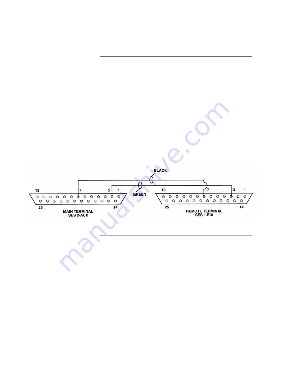
to a remote terminal when properly configured (see Figure 3).  Using this port’s 
output allows two-wire data transmission (XMIT & GND) to remote 4190-9006 
terminals that function as remote monitors.  The remote terminal is configured 
like a 2120 terminal and then used without a keyboard. 

Note:  

For the 2120 system, the Aux Port is commonly used for remote 
monitors.  The 4010, 4020, and 4100+/4120 systems do not support a 
remote monitor. 

The Aux Port is capable of having ten 4190-9006 terminals connected to it as 
long as the wiring distance to any terminal does not exceed 2,500 feet and the 
total capacitive load of the circuit wiring does not exceed 1.25 mfd.  Since each 
terminal has an Aux Port, it’s possible to repeat the data as necessary from each 
remote terminal. 
 
Refer to Figure 3 to connect from the Aux Port to a remote terminal.  If using 
shielded cable, connect the shield to the GND terminal. 


Figure 3.  Aux Port Connections to Remote Terminal 


2120 Remote Terminal Connections 

Connecting to a Remote 
Terminal for 2120 Systems 

firealarmresources.com

Содержание 4190-9006

Страница 1: ...TATIC HAZARD Static electricity can damage components Therefore handle as follows 1 Ground yourself before opening or installing components use the 553 484 Static Control Kit 2 Keep uninstalled component wrapped in anti static material at all times The 4190 9006 Remote CRT Keyboard provides a remote visual indication of system events for the 2120 Multiplex System 4010 4020 Fire Alarm Control Panel...

Страница 2: ...erminate the loose ends of the 733 812 cable to a DB 25F connector Use Tables 3 4 and 5 to connect the loose ends of the 733 812 cable directly to a 2120 4010 4020 or 4100 4120 2 Connect the keyboard 3 Plug in AC power using the power cord Connections Connecting to a 2120 4010 4020 or 4100 4120 System Figure 1 Rear View of Terminal Note See 733 812 Cable Terminations on Pages 2 and 3 firealarmreso...

Страница 3: ...MUX Wire Lead Connection Red lead XMIT TB3 11 Black lead RCV TB3 10 Green lead GND TB3 6 White lead Cut off not used Figure 2 DB 25F Connector Pin Layout Table 3 Connecting to the RS 232 Board of a 4100 4120 Wire Lead Connection Red lead XMIT Pin 3 of a DB 25F connector Black lead RCV Pin 2 of a DB 25F connector White lead CTS Pin 5 of a DB 25F connector Green lead GND Pin 7 of a DB 25F connector ...

Страница 4: ...B1 4 or TB1 9 Green lead GND TB1 4 or TB2 5 TB1 5 or TB1 10 Note PORT A PORT 1 TB1 PORT B PORT 2 TB2 Table 5 Connecting to the RS 232 Board of a 4010 FACP Wire Lead Connection Red lead XMIT P6 2 Black lead RCV P6 1 White lead CTS P6 5 Green lead GND P6 3 Note 1 P6 PORT B Note 2 P7 PORT A does NOT support a CRT Cable Terminations Continued 733 812 Cable Terminations for 4010 4020 and 4100 4120 Syst...

Страница 5: ...te monitors The 4010 4020 and 4100 4120 systems do not support a remote monitor The Aux Port is capable of having ten 4190 9006 terminals connected to it as long as the wiring distance to any terminal does not exceed 2 500 feet and the total capacitive load of the circuit wiring does not exceed 1 25 mfd Since each terminal has an Aux Port it s possible to repeat the data as necessary from each rem...

Страница 6: ...ll Length 350 ms Setup Language U S Sessions One Display Setup F3 Command Specification Display Cursor ON Cursor Blink Block Auto Adjust Cursor ON Page Length 25 Screen Length 26 lines Screen Video Normal Columns 80 Scroll Jump Overscan Borders ON Width Change Clear OFF Speed Fast Refresh Rate 71 Hz Keyboard Setup F4 Command Specification Language U S Char Set National Key Mode ASCII Key Click ON ...

Страница 7: ...p F7 Command Specification Comm Mode Full Duplex Local OFF Null Suppress OFF Break 250 ms Modem Control OFF Disconnect 2 Seconds Recv cr cr Recv DEL Ignore Send Ack ON Alt Input Data ON Send Block Term None Send Region Term Screen Send End Region Print Setup F8 Command Specification Print Mode Auto Print National Print Region Screen Print Block Term None Secondary Recv ON 4100 4120 values are show...

Страница 8: ...tion Answer Back Mode ON Answer Back Conceal Prog Setup F12 Command Specification Key F1 Program Fkey Key Dir Comm Dependent After making configuration selections save configuration by pressing the F14 key Note The F14 key takes the terminal off line and returns it on line If the terminal ever fails to respond press the F14 key For more information refer to the User s Guide supplied with the termi...

Страница 9: ...G SIL command follow Steps 5 through 8 5 Press the DOWN ARROW key and move to the F7 box on the screen Press the RETURN key and highlight the F8 box 6 Press the DOWN ARROW key and move to Text field 7 Press and hold down the CTRL key and press the S key This prompts a display of ù on the screen 8 Press the DOWN ARROW key to move to Label field and type SIG SIL To program the Detector Reset command...

Страница 10: ...gain to confirm that you want to add an RS 232 card A message appears indicating that the system is configuring the card Press the EXIT key once to move back one menu level and then continue below with Step 5 in the next section Use the following steps to configure the printer settings baud rate etc for the RS 232 port to which the printer is attached Before beginning ensure you know the hardware ...

Страница 11: ...mn printer Unused PRT40S Supervised 40 column printer PRT40U Unsupervised 40 column printer PRT80S Supervised 80 column printer 9 Use the arrow keys to move the bracket to the BAUD Parameter Use the NEXT and PREVIOUS keys to select a choice for this parameter Choices are as follows 1200 2400 4800 9600 19200 38400 10 Use the arrow keys to move the bracket to the PARITY parameter Use the NEXT and PR...

Страница 12: ...e appears indicating that the configuration has changed Move to the SAVE CFIG choice and press ENTER Another message appears asking you to confirm the Save operation Press ENTER to save the new CFIG Table 6 Routing Specific Events Prompt Default Setting Explanation Send Fire Events to Port Yes Routes information on all fire alarms to the printer Send Supervisory Events to Port Yes Routes informati...

Отзывы: