page 3
579-1317 Rev 1
Sounder and Sounder Beacon Installation Instructions
Installation
Dimensions
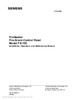
Weatherproof wall units
Indoor wall units
Base units
105mm/4.1in.
97mm/3.8in.
153mm/6in.
32mm/1.25in.
39mm/1.5in.
60mm/2.4in.
65mm/2.6in.
39mm/1.5in.
32mm/1.25in.
5
146mm/5.7in.
Figure 1: Sounder Beacon
89mm/3.5in.
40mm/1.6in.
138mm/5.43in.
60.3mm/2.37in.
135mm/5.3in.
Figure 2: Sounder
45mm/1.77ijn.
114mm/4.48in.
70mm/2.75in.
50mm/1.96in.
1
2
Figure 3: Base unit
1. Temporary park plunger and indicator (yellow)
for short circuit isolator.
2. Address flag holder.
Wiring
Wall variant wiring
Base variant wiring
Contact and Function
+
-
+
-
Loop in
Loop out
Screen
Figure 4: Wall variant wiring
Loop positive
Loop positive
Loop negative
Loop negative
Optional remote indicator
-
-
L1
L
R
M
L2
Figure 5: Base variant wiring
L: Not used
L1: Positive line in and
out
L2: Negative line
(isolator in and out)
M: Negative line (isolator
in or out)
R: Remote LED out,
wired only if a remote
indicator is required.
Wiring notes
• All wiring must comply with local installation regulations and local fire system design requirements.
• Ensure all conductors are free of earths.
• Verify correct wiring and wiring polarity before connecting the devices to the addressable loop.
• Cables are to be selected in accordance with local standards, and with document 17A-02-D: MX Range of Addressable Controllers.
firealarmresources.com