background image

13-5

4007ES Panel Programmer Manual (

579-1167)

Adding or Editing Network Information, 

Continued

Procedure to 
Declare Public 
Points

Use the following procedure to define the panel’s public points.

1. Click on the 

Network

 tab shown in the upper right corner of Figure 13-1.

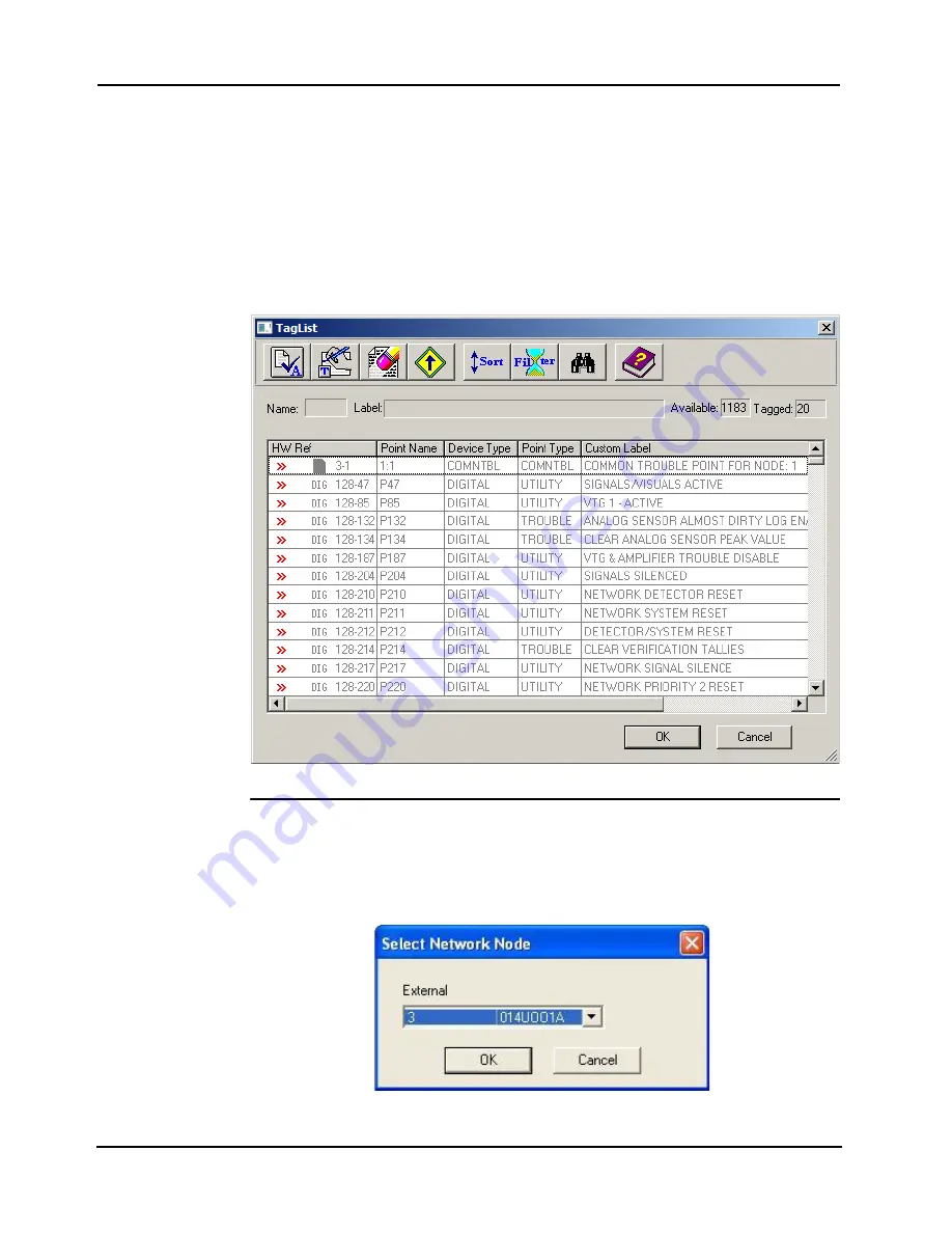
2. Right click on the Public Points folder and select the 

Edit Public

 choice. The tag list is 

shown in Figure 13-3.

3. Position the highlight on a point and press the space bar to tag the point. A >> symbol is 

shown to the left of the point to indicate that it is selected. (To remove this symbol and 
deselect a point, highlight the point and press the space bar again.)

To select a contiguous group of points, click on the first point in the group, press the SHIFT 
key and click on the last point in the group you want to select.

Figure 13-3. Public Points Tag List

Procedure to 
Declare External 
Points

Use the following procedure to define the panel’s external points.

1. Right click on the External Points folder and select the 

Edit Externals

 choice. The dialog 

shown below appears. Click on the drop down list box and select the number of the node 
containing the points you want to declare external.

Figure 13-4. Select Network Node

Continued on next page

Содержание 4007ES Panels

Страница 1: ...4007ES and 4007ES Hybrid Fire Alarm Systems Programmer s Manual 579 1167 Rev D...

Страница 2: ......

Страница 3: ...scope or other focusing equipment when viewing the output of this device FCC RULES AND REGULATIONS PART 15 This equipment has been tested and found to comply with the limits for a Class A digital devi...

Страница 4: ......

Страница 5: ...xisting Jobs 3 2 Setting Job Preferences 3 2 Job Notes 3 3 Saving Jobs 3 3 Building a Job 3 3 System Requirements 3 4 Archiving a Job 3 4 Backing Up a Job 3 4 Chapter 4 Panel Information and Configura...

Страница 6: ...ting the Event DACT Card 6 15 48 LED Module 6 17 Chapter 7 Editing TrueAlert Devices Properties 7 1 Introduction 7 1 Point Editing for TrueAlert Device 7 2 TrueAlert ES AO Appliance Point Editing 7 2...

Страница 7: ...ate an Equation 9 3 Custom Control Window 9 5 Selecting User Program 9 6 Adding Input Statements 9 7 Adding Output Statements 9 8 Floor Above Floor Below Wizard 9 8 Selecting Floor Tab 9 9 General Inf...

Страница 8: ...Self Test Triggering Point and Point List 9 37 Chapter 10 File Transfer 10 1 Introduction 10 1 USB File Transfer 10 2 USB File Transfer 10 2 Files Transferred 10 3 IP File Transfer 10 4 IP File Trans...

Страница 9: ...Programming Distributed Network Silence 13 8 Programming Central Network Reset 13 9 Programming Distributed Network Reset 13 10 Distributed Configuration 13 11 Chapter A ULC Programming Requirements...

Страница 10: ......

Страница 11: ...th the ES Panel Programmer Requirements To install and open the Programmer the user must have the following Internet access in order to download the software Downloading the Software To download the 4...

Страница 12: ...the computer Note Before restarting the computer be sure that all open files have been saved 7 Click on Finish to restart and complete the installation Starting the Programmer To Start the ES Panel Pr...

Страница 13: ...ption Menu Item Description New Creates a new job Archive Archives the job Open Opens an existing job Backup Backs up the job Close Closes the current job Restore Restores the previous saved version o...

Страница 14: ...t Allows the user to access the following sub tabs General List Latching Supv Verification Alarm Verification WalkTest and Elevator Recall Custom Control Allows the components of the ES Panel FACP to...

Страница 15: ...the user to Serial Enable a serial connection between the FACP and the Perle Box This option cannot be used for panel serial downloads Network Enable a network connection between the computer and the...

Страница 16: ...save the current job Cut Click to cut the selected information from its current location Copy Click to copy the selected information Paste Click to paste cut or copied data Print Click to print the cu...

Страница 17: ...nents in a branch structure Grid View Display the panel components in a grid structure Point NA Display the list of all the points in the FACP Double click on any of the points to view and edit their...

Страница 18: ......

Страница 19: ...e job type 4007 for the addressable panel 4007H for the Hybrid panel 3 Enter the job number The job name should be 8 characters long and start with a number Year This is a two digit field Use the last...

Страница 20: ...r generates a reminder dialog each time you exit a screen whose corresponding entry in the Programmer Task Checklist has not been marked as complete For example if you view the General Information tab...

Страница 21: ...444 appears and the job folder 333 is empty Note Conventionally performing a Save As Copy is the first action a technician takes when opening an existing job to create a new revision This way if comp...

Страница 22: ...Cancel the operation This will result in an error file and the programmer will return to the last saved job 7 The archived file will then open as a read only job To save the job as a different version...

Страница 23: ...s information about the branch of the company and other useful information Notice to users Installers AHJ and other Involved Parties 4 1 Panel Information 4 1 Passcode Configuration 4 8 System Options...

Страница 24: ...e by day month and year example January 4th 2013 04 01 13 Time Format Select 12 Hour dflt for the panel to display the time as a m and p m example 6 00 a m 6 00 p m Select 24 Hour for the panel to dis...

Страница 25: ...for Non Steady Audible Evacuation Signals The term Non Steady Audible Evacuation Signal refers to any Notification Appliance capable of sounding a coded signal The default setting for this option is n...

Страница 26: ...ver this option See description of Alarm Silence Reset Inhibit below for more information The range for this option is 60 3600 seconds The default setting for this option is not enabled Set the point...

Страница 27: ...pv Reminder The Supv Reminder option programs the system to periodically sound the piezo if an uncleared supervisory condition exists at the panel thereby reminding system operators about the uncleare...

Страница 28: ...ches must be set to the correct setting For example if a specific candela value is selected in the system options the device should be set to FACP On the other hand if system option is set to Hardware...

Страница 29: ...y to open its Object Properties window 3 Select one of four user levels for the display function Basic display functions such as System Reset and Change Time and Date are usually assigned to user leve...

Страница 30: ...the passcode 5 Click on OK to confirm the selection Features Configuration The Features sub tab provides information on the functionalities of the ES Panel Programmer which can be used with the softw...

Страница 31: ...ht hand side of the screen and a work area on the left hand side of the screen There are two available views Tree View This view displays the hardware in a branch structure The hardware appears linked...

Страница 32: ...t corner of the work area The panel icon represents all of the non networked RUI linked components controlled by a single CPU A single panel may for example actually be multiple boxes some residing at...

Страница 33: ...AC power supply then double click on IDNet Multiloop 2 Click on the Loop Editing tab 3 Select the first unused card 2 loop B isolator 4 Change the device type to Isolator Expanded point capacity 5 Rep...

Страница 34: ...nunciator cards of the same type added to the same unit also shares this number When an additional annunciator card of a different type is added to the unit that annunciator card is given an annunciat...

Страница 35: ...function location or some other descriptive text Unit Box Bay and Block location The values shown in the fields reflect the location in which the card icon was placed when you added it with the progr...

Страница 36: ......

Страница 37: ...6 1 Enter the card s custom label This label should make the card easily identifiable The following fields in the tab are filled by the programmer and cannot be edited Card address Card description Ca...

Страница 38: ...indow Figure 6 2 This tab allows you to set the access level for the various system operations that can be carried out via the service port To set an access level for one of the service port operation...

Страница 39: ...Alarm Display scrolling Supervisory display scrolling Disable display scrolling To set the properties 1 Click on the Hardware tab 2 Expand the unit the box and the bay combination in which the annunci...

Страница 40: ...programmer and cannot be edited Reference Label Point Point Type For each LED 1 Select the appropriate mode from the drop down list 2 Enter a reference address Note Depending on the switch mode a LED...

Страница 41: ...Access Levels tab The Access Level tab of the color user interface card cannot be edited You can view the access level for the various functions in the system but cannot change them Figure 6 6 Color...

Страница 42: ...he power supply card The choices are None City Connect Relay Figure 6 7 IDNAC Data Entry Tab 3 Click in the 25V Regulator box if a 25V regulator card 4007 9802 is used with the FACP 4 Click OK to conf...

Страница 43: ...DCAI Custom label Loop 1 address filled by the programmer Loop 2 address Unused need to be assigned by the person programming the panel Custom Label TrueAlertES Appliances AV Audible Visual VO Visual...

Страница 44: ...et point easily identifiable Figure 6 11 IDNet Multiloop Point Editing Window 5 Tag the IDNet point to a Zone by clicking on Zone List The TagList window is displayed Figure 6 12 a Scroll through the...

Страница 45: ...er Bay number Location To edit the Data Entry tab Figure 6 14 1 Configure the Depleted Battery Cutout option If selected the power supply card shuts itself off after detecting a depleted battery condi...

Страница 46: ...p down list 3 Enter a custom label This label should make the point easily identifiable 4 Select the EOL resistance from the EOL Resistance drop down list 5 Click Apply OK to confirm the edits To edit...

Страница 47: ...or address Unit number Box number Bay number To edit the Point Editing tab Figure 6 17 1 Select the device type The choices are MONA Class A Monitoring Device Note If MONA is selected for a point a co...

Страница 48: ...l the points on the card to match the auto fill selection Point Forward programmer changes the highlighted point and all subsequent points on the card to match the auto fill selection Selected program...

Страница 49: ...count Numbers Primary 1 Secondary 2 Account 1 Account 2 Central Station Line Dial Mode Tone Pulse Tone else Pulse Miscellaneous Report AC Failure Delay Test Report Time Send Unmapped Points IP Communi...

Страница 50: ...e Point Types tab Figure 6 22 The Point types tab allows you to add new point types delete or edit existing point types To edit an existing point 1 Click on a point in the grid 2 Edit the appropriate...

Страница 51: ...T Card The 4007 9806 DACT per event has five main tabs To edit the Card Properties tab the Basics tab the Event Codes tab the Local Points tab and the Points tab To edit the Card Properties tab per ev...

Страница 52: ...available when 3 1 4 2 or BFSK is selected Format rate 10 PPS or 20 PPS Communication Format Frequency 1 9KHz Data 1 4KHz ACK or 1 8KHz Data 2 3KHz ACK Dual Mode Tone Pulse Tone else Pulse Miscellaneo...

Страница 53: ...al columns 4 Click Apply OK to confirm the edits To edit the Points tab Figure 6 23 1 To edit a point click on the point or use the up and down arrow with the spacebar to toggle point selection 2 Depe...

Страница 54: ...t Editing tab From the Point Editing tab two view choices are available High Level Modes organizes the LEDs in pairs Under this view the Mode options are more limited OO On Off TO Trouble On Low Level...

Страница 55: ...tifiable 5 When editing the 8 points of the Display Column 6 LED pairs can be either yellow red or yellow green 6 Repeat for each point that needs to be edited In Low Level Mode 1 Select a column and...

Страница 56: ......

Страница 57: ...lert ES VO Appliances Point Editing 7 3 TrueAlert ES VO H Appliances Point Editing 7 4 TrueAlert ES VO L Appliances Point Editing 7 5 TrueAlert ES VO LH Appliances Point Editing7 6 TrueAlert ES AV App...

Страница 58: ...ttern consisting of three second pulses each separated by a second silence Each three pulse group is separated by 1 seconds of silence Pattern repeats until alarm silence March 20 A coded signal that...

Страница 59: ...candela value to the one selected in the System Option tab 15 candela 75 candela WP 75 candela WP 185 candela Hardware Selecting this option sets the appliance to the setting indicated on the applianc...

Страница 60: ...ing this option sets the candela value to the one selected in the System Option tab 110 candela 135 candela 185 candela Hardware Selecting this option sets the appliance to the setting indicated on th...

Страница 61: ...Default Selecting this option sets the candela value to the one selected in the System Option tab 15 candela 30 candela 75 candela Hardware Selecting this option sets the appliance to the setting indi...

Страница 62: ...stem Default Selecting this option sets the candela value to the one selected in the System Option tab 110 candela 135 candela 175 candela Hardware Selecting this option sets the appliance to the sett...

Страница 63: ...ets the candela value to the one selected in the System Option tab 15 candela 30 candela 75 candela 110 candela 135 candela 185 candela Hardware Selecting this option sets the appliance to the setting...

Страница 64: ...pulse coding pattern consisting of three second pulses each separated by a second silence Each three pulse group is separated by 1 seconds of silence Pattern repeats until alarm silence March 20 A co...

Страница 65: ...ion sets the candela value to the one selected in the System Option tab 110 candela 135 candela 185 candela Hardware Selecting this option sets the appliance to the setting indicated on the appliance...

Страница 66: ...ttern repeats until alarm silence March 60 A coded signal that uses 60 beats per minute Each beat consists of second pulse on second off Pattern repeats until alarm silence March 120 A coded signal th...

Страница 67: ...ela options System Default Selecting this option sets the candela value to the one selected in the System Option tab 15 candela 30 candela 75 candela Hardware Selecting this option sets the appliance...

Страница 68: ...attern repeats until alarm silence March 60 A coded signal that uses 60 beats per minute Each beat consists of second pulse on second off Pattern repeats until alarm silence March 120 A coded signal t...

Страница 69: ...e candela options System Default Selecting this option sets the candela value to the one selected in the System Option tab 110 candela 135 candela 185 candela Hardware Selecting this option sets the a...

Страница 70: ...Pattern repeats until alarm silence March 60 A coded signal that uses 60 beats per minute Each beat consists of second pulse on second off Pattern repeats until alarm silence March 120 A coded signal...

Страница 71: ...tions Option Description Custom Label This field can be used to describe the appliance s function location or other descriptive information Table 7 11 Repeater Editing Options Option Description Custo...

Страница 72: ...e information Loop 1 Address The Loop 1 Address is automatically set by the programmer Loop 2 Address This virtual address does not need to be adjacent to the loop 1 hardware address Table 7 13 TrueAl...

Страница 73: ...Option tab Temporal A three pulse coding pattern consisting of three second pulses each separated by a second silence Each three pulse group is separated by 1 seconds of silence Pattern repeats until...

Страница 74: ...ociated respectively with the ALL VISUAL and ALL AUDIBLE VNAC by default Candela Select the candela output of the appliance Coding Type Select the Coding Type to set the cadence of the audible signal...

Страница 75: ...strobes LEDs can be programmed to monitor a list and turn ON when any point in the list activates Custom Control equations typically use lists of monitor points to indicate when a specific output act...

Страница 76: ...mn drop down list box to select the criteria to use for the sort Next select whether the sort should be in Ascending or Descending order and click on OK Custom Label Spell Check Spell Check allows you...

Страница 77: ...autogen on and cannot be edited This symbol represents an auto generated list with the autogen property turned off Indicates that the list is not automatically generated A system list s autogen prope...

Страница 78: ...n the Tag by Type dialog to tag points based on their point type or device type Click on Clear All Tags eraser to erase all the tags Click on Tags Up to sort the tagged points to the top of the list C...

Страница 79: ...operation for the alarm verification feature To select Canadian or Domestic US operation Figure 8 3 follow these steps 1 Right click on one of the groups and select Properties The Alarm Verification P...

Страница 80: ...ent WalkTest on the system Whether logging of WalkTest information is enabled or not Enable this option to perform a silent WalkTest Refer to the 4007ES Operator s Manual 579 1165 for information on s...

Страница 81: ...en the list of options appears select Tag List b In the Tag List use the mouse or arrow keys to highlight each monitor point you want to move into the group Press the space bar to tag or un tag points...

Страница 82: ...one group to another However at a later point if you recheck this box the points you previously moved to other groups will be moved back to Group 1 Control A check in this box means control points sig...

Страница 83: ...acebar to tag or un tag points to be added or deleted A point is selected when a symbol appears to the left of the point c Repeat these steps to move other monitor points into the group d Points that...

Страница 84: ...ist tab provides a way to group alarm conditions into zones up to 512 zones When grouped into zones when an alarm occurs a list of affected zones is displayed on the panel s touchscreen It is then pos...

Страница 85: ...tem following an alarm condition prevents supply fans from feeding a potential fire and makes it possible for the HVAC system to exhaust smoke from the area in alarm In this case custom control equati...

Страница 86: ...ned list called Floor 1 Pull Stations and populating it with only the pull stations from floor 1 provides a way to monitor all of the pull stations on the floor without writing an equation for each pu...

Страница 87: ...on to execute In the following example if either Zone1 or Zone2 enters an alarm state the output Hold ON SIG3 executes Figure 9 4 Logical Operator OR NOT Operator Use the NOT Operator to specify that...

Страница 88: ...tor by positioning the inputs beside one another Figure 9 6 Logic Diagram The example shown above can be interpreted as If point M2 1 or M2 2 or M2 3 and M2 4 are in a trouble state hold on Relay 1 M2...

Страница 89: ...The right half of the window is used for creating user defined Custom Control equations With the Equation Comment text entry box you can enter descriptive text explaining the operation of the equatio...

Страница 90: ...To add a new custom control equation 1 Right click on one of the user programs located at the bottom of the program list and select Add Equation from the list of options Figure 9 8 Add Equation 2 The...

Страница 91: ...9 10 Positioning the Cursor 2 Click Add The dialog shown in Figure 9 11 appears Figure 9 11 Select Input Opcode Dialog 3 Click on the drop down list box select one of the Opcodes and click Next Opcode...

Страница 92: ...ode available Select Item Set Reset Priority Select Point 4 The next dialogs displayed by the wizard depend on the Opcode you selected in Step 3 Follow the Wizard s windows to create the output for th...

Страница 93: ...t of the Custom Control window 2 Right click in the blank area above the tab When the list of options appears select Create Floor Group The ES Panel refers to each set of floor above below equations a...

Страница 94: ...tion is to be stored Three programs are available for user programs Number of Floors This specifies the total number of floors controlled by the floor above below equations Control of Floors Above Whe...

Страница 95: ...Audio Points Identifies the floor s non audio horns strobes notification points Air ON Points Identifies the pressurization fan and damper ON points Exhaust ON Points Identifies the exhaust fan and d...

Страница 96: ...loor 2 Figure 9 18 Selective Signaling Selecting Selective Signaling Wizard Tab Start the Selective Signaling Wizard by clicking on the Selective Signaling Wizard tab which is located along the bottom...

Страница 97: ...by the application Type select all that apply Visual Select to use visual notification appliances in the application Audible Select to use audible notification appliances in the application TrueAlert...

Страница 98: ...n Notification Points in this Signal Zone click the notification appliance you want to turn on when the tagged initiating devices activate The choices are Visual Points Audible Points TrueAlert Zones...

Страница 99: ...rol window 2 Right click in the blank area above the tabs When the list of options appears select Create Point Group A figure similar to appears Figure 9 24 Creating Point Group 3 Enter a Name for the...

Страница 100: ...silence Figure 9 26 Specifying Device Operation Note List number L256 is the next available list It is not specifically L256 4 Click on the Group Points button A tag list containing single station po...

Страница 101: ...IVE EARTH ON RUI OR STATUS ON 1 0 28 CARDSTAT CSP NEGATIVE EARTH ON RUI OR STATUS ON 2 0 8 CARDSTAT CSP IDNET EARTH TROUBLE END INPUTS OUTPUTS TRACK ON PRI 9 9 P535 DIGITAL UTILITY COMMON GROUND FAULT...

Страница 102: ...pattern and no distinct pre discharge tone pattern plays Alarm Triggered by Activation of Manual Release Station If a delay timer is used the system plays a 120 BPM signal on the NACs as the timer cou...

Страница 103: ...esive appliqu 4010 9830 English or 4010 9830CAF French must be ordered separately and applied to the front door of the unit when it is used as a suppression release system This appliqu is used to indi...

Страница 104: ...signals relays L139 Local Mode Operation Points RELVIS Release visual circuit SIGA SIGB CHAN2A CHAN2B CHAN4A CHAN4B PCHAN4A PCHAN4B SBZAM SAZAM SIGIAM NULLSIG PS_SIGA PS_SIGB MFIO_SIGA MFIO_SIGB MSOUN...

Страница 105: ...901 MS502EX MU901 MU912 S251 S252PLUS All PHOTO Device types All ION Device types all HEAT Device types L18 General Fire Alarm Monitor Zones L30 Alarm Verification Group 0 L61 Coding Group 1 Monitor Z...

Страница 106: ...ted in this section Specific configuration is listed under each use case Panel A 4007ES IDNAC with the following points IDNet points Manual release point MBZAM with SSDUMP point type at address M1 11...

Страница 107: ...Release Warning Points and select SIG914 Press Suppression Dump Points and select SIG3 and M1 36 0 Press Release Notification Audible NACs and select SIG913 Use Case 1 10 Second Delay Abort Specific...

Страница 108: ...ISIG turns off RELWVIS turns on RELSIG turns on at high cadence March120 Press and release the abort switch Automatic Release Timer countdown is reset to the original value RELISIG turns on steady for...

Страница 109: ...1 2 Comments n a Continued on next page Table 9 5 IRI Abort Actions and Releases Action Response First detector is triggered RELSIG turns on low cadence Temporal RELWVIS turns on Abort switch is pres...

Страница 110: ...t at 0 Hazard Area Lists window Press Manual Release Points and select the manual release point at M1 11 0 Press Automatic Release Points and select Automatic Release Points at M1 18 0 Do not add any...

Страница 111: ...one shown in Figure 9 29 appears Figure 9 29 Create Hazard Area Menu Choice 3 Right click on the blank area of the screen labeled Hazard Area 4 Click on Create Hazard Area from the menu that appears A...

Страница 112: ...er Monitor cards or ZAMs Dual detector operation which requires two detectors to activate can use TrueAlarm initiating devices First Stage Audible Notification Click on the drop down list box and set...

Страница 113: ...ed system or a single detector in a single alarm system the Suppression Release peripheral activates its output after a 10 second delay 10s Remaining Similar to the 10 Second Delay except when the abo...

Страница 114: ...ls turn on Evacuation audibles turn on at 120 BPM Reload the Automatic Release Timer with the programmed value If the abort switch is pressed and released after the second alarm while the investigatio...

Страница 115: ...he alarm before the second confirmed alarm Implementing a delay on the second alarm gives time for occupants to evacuate and where required for the ventilation fans and dampers to shut down prior to t...

Страница 116: ...o select The TagList screen shown in Figure 9 35 appears 2 The TagList screen displays all points with the relevant suppression release point type To select a specific point for inclusion in the hazar...

Страница 117: ...re 9 36 Use the scroll bar to check the selections for all options If necessary click Back to return to one of the option selection screens to change a choice When all of the options are set correctly...

Страница 118: ...azard Area The wizard screens reappear in sequence Reselect the options for the hazard area as necessary Properties Right click on the name of an existing equation and select Properties A properties s...

Страница 119: ...point can be added to the job as external point and used to trigger a self test The user can run an automatic self test at any time and on multiple panels at the same time Important The system pseudo...

Страница 120: ...re stored No specific program number is reserved for use by Self Test equations Click Next Figure 9 41 Initial Data Screen Step 2 Selecting Start Time and Frequency of the Self Test To select time and...

Страница 121: ...est Triggering Point and Point List Table 9 7 Default Values for the Self Test Wizard Settings Setting Value User Options Input Validation Self Test Time 2 00 am User can edit hour and minute Weekly N...

Страница 122: ...9 38...

Страница 123: ...re explained in this chapter For the 4606 Series Color Touchscreen LCD Annunciator the preferred file transfer method is also to use USB portable storage device Partial file transfer can also be perfo...

Страница 124: ...The Master BIN file version appears on the 4007ES panel display and it is different from the 4100ES and 4010ES BIN files 4 Save the job build it and then re open it using the most recent version of t...

Страница 125: ...ice by pressing the Eject USB button located under the Mass Storage The panel has now been upgraded with a new job and the latest software Files Transferred The following is an example of the files th...

Страница 126: ...rol Panel FACP software features Panel Exec Slave Exec etc This provides a means for recovering previous configurations via the File Transfer History Undo tab This also makes it possible for the FACP...

Страница 127: ...ch the slave module operates Occasionally changes to the functionality of a slave module may require you to download a new slave Exec file For example a change to the IDNet Slave Exec file may be nece...

Страница 128: ...10 6 4007ES Panel Programmer Manual 579 1167 IP File Transfer Continued Download Tab By default the IP File Transfer window opens to the Download tab Figure 10 6 IP File Transfer Download Tab...

Страница 129: ...program s default setting When the system reboots If the Apply download changes after download button is not selected the downloaded changes will be saved and applied once the system is rebooted Exclu...

Страница 130: ...e is given a descriptive name appended with the current date e g AlarmLog_2010_3_11 txt Figure 10 7 Upload Reports Tab To upload a file or a report 1 Click on the Upload Reports tab near the top of th...

Страница 131: ...viding the following information for each point Device Number Custom Label Current Sensitivity of the Point Point Status Normal Trouble Alarm Almost Dirty Status Points that are almost dirty have an a...

Страница 132: ......

Страница 133: ...port or the DACTs A window similar to the one shown in Figure 11 1 appears Figure 11 1 Port Vectoring Tab 2 In the Available Ports list located on the left side of the window click on the line contai...

Страница 134: ......

Страница 135: ...ould interpret i e react to incoming analog data from the device attached to the ZAM This point type can then be assigned to the ZAM using the IDNET point editing screen which is accessible through ei...

Страница 136: ...are as follows Decimal Display This field specifies the degree of precision for the device reporting data how many digits after the decimal place the device reports If the device reports data one unit...

Страница 137: ...Type in Step 2 when the device being measured goes above the value that you specify in the Unit field Unit Field This is the value that the device must pass to trigger the alarm condition 7 Click Fini...

Страница 138: ...point 1 Right click on the point you want to modify 2 Click on Properties 3 Modify the AMON Properties as required Figure 12 5 Editing an AMON Point Type 4 Click Apply OK Deleting a Point To delete a...

Страница 139: ...nts to report to a central annunciator such as a TSW you would use the ES Panel programmer to declare the panel s points or a subset of its points public Likewise on the TSW you would declare the pane...

Страница 140: ...nce Avoid Version Mismatch If you change a label or device type or point type on a point that is EXTERNAL to other nodes you must build and download all nodes that have an external copy of the point I...

Страница 141: ...k Information The network information fields are contained within the Panel tab To access these fields do the following 1 Click on the Network tab shown in the upper right corner of Figure 13 2 2 Clic...

Страница 142: ...nitialization Checking this option prevents analog detectors from sending status on initialization if the value is not an alarm or trouble condition However if the analog value indicates an alarm or t...

Страница 143: ...indicate that it is selected To remove this symbol and deselect a point highlight the point and press the space bar again To select a contiguous group of points click on the first point in the group...

Страница 144: ...t a point highlight the point and press the space bar again To select a contiguous group of points click on the first point in the group press the SHIFT key and click on the last point in the group yo...

Страница 145: ...mer Open the job for the node you have designated as the Central Network Silence Node 2 When the ES Panel programmer appears click on the Network tab at the top of the programmer When the Network wind...

Страница 146: ...ag List When the list of choices appears click on the Network Externals check box Click on the OK button All of the External Points appear 8 Click on each entry for P217 Network Signal Silence each no...

Страница 147: ...ogrammer appears click on the Network tab at the top of the programmer When the Network window appears click on the Network Points subtab at the bottom of the Network window 3 Right click in the Netwo...

Страница 148: ...et and 105 External Entire System Reset Points Figure 13 10 Distributed Network Reset To configure Distributed Network Silence do the following on each node 1 Open the network job using the network pr...

Страница 149: ...job its L170 is automatically updated to include the imported digital pseudo point The same applies to P464 and L171 So when the remote node P463 is turned on default SMPL equation 0 164 will turn th...

Страница 150: ......

Страница 151: ...on This appendix describes ULC programming requirements In this chapter Required Operations A 2 Alarm Cutout Timer Feature A 4 Releasing Specific Controls and Indications A 7 Appendix A ULC Programmin...

Страница 152: ...ard Properties section of the Color User Interface properties Follow the steps outlined below to program the ULC required items 1 Click the Hardware tab and expand the Unit 0 Box 1 Bay 1 and Block A i...

Страница 153: ...ntinued Procedure Figure A 2 Color User Interface Properties with S527 Operation Check Box Note In compliance with ULC requirements the slide in label for LEDs on the user interface must be labeled as...

Страница 154: ...g the LED Step 1 Assigning a digital pseudo point for the LED 1 Click the Point tab 2 Scroll until the points with the Digital device type are visible Select a point which has an empty custom label fi...

Страница 155: ...Point Figure A 6 Custom Control Equation to Turn OFF Pseudo Point Step 3 Program the LED to reference the assigned pseudo point 1 Review the section detailing how to program the LED module see Chapte...

Страница 156: ...A 6 4007ES Panel Programmer Manual 579 1167 Alarm Cutout Timer Feature Continued Programming the LED Figure A 7 LED Module Properties...

Страница 157: ...e additional LED Module 4007 9805 2 If you have multiple Hazard Areas repeat the steps below for each Hazard area as required Label the insert for the LEDs appropriately to identify the function and t...

Страница 158: ...quation to turn off the LED when the zone releases 4 Write or add to an existing equation the equation to turn off the digital pseudo during system startup or upon system reset 5 Choose an available R...

Страница 159: ...he LED clears upon system reset or when the solenoid is deactivated Below is an example program 1 Click the Custom Control tab 2 Click the Suppression Release Wizard subtab 3 Right click the title nex...

Страница 160: ...tal pseudo point that was assigned Abort Switch Trouble during Normal Supervisory Conditions This programs the panel such that an abort switch causes a trouble when activated during normal supervisory...

Страница 161: ...ppression Release Wizard that you are working on right click the title next to the wizard graphic and select Properties to open the Hazard Area 4 Select the points tab and write down the lists assigne...

Страница 162: ...s referenced for status SUPV change it to ABNORM For example 7 Add a HAZNAME Abort Switch Trouble equation to annunciate troubles from this abort switch as shown below when the hazard area is not in a...

Страница 163: ...warning to released will not re sound the warning NACs An example program follows In this example both the visual and audible Release Notification NACs are silenced See the following for a program exa...

Страница 164: ...he system AND someone is pressing the RSSS button indicated by the pseudo chosen for the button the output holds the NACs off at a higher priority than releasing would normally turn them on If your jo...

Страница 165: ...equation written by the Suppression Release Wizard to silence the NACs on system silence If it is not deleted it will still silence the hazard area a Right click the wizard for that hazard and select...

Страница 166: ...A 16...

Страница 167: ......

Страница 168: ...2015 2016 Tyco Fire Protection Products Specifications and other information were current as of publication and are subject to change without notice 579 1167 Rev D...

Отзывы: