background image


22 


1. 

Description du gerbeur 


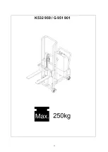
Aperçu des principaux composants de la série EZ 


23.


Cadre 

24.


Vérin hydraulique 

25.


Porte-fourche 

26.


Fourche réglable 

27.


Roue avant 

28.


Roue guide 

29.


Contrepoids 

30.


Boîtier de commande 

31.


Commutateur à clé 

32.


Touche levage 

33.


Touche abaissement 

Содержание EZ2515

Страница 1: ...K 532 959 G 951 901...

Страница 2: ...olatot vel nk NL Een handleiding is ook beschikbaar in uw taal Neem a u b contact met ons op N Ogs p ditt spr k ligger det en brukerh ndbok klar til avhenting Ta kontakt med oss PL Na danie dost pna j...

Страница 3: ...Staplers bersicht der Hauptbestandteile der Serie EZ 1 Rahmen 2 Hydraulikzylinder 3 Gabeltr ger 4 Verstellbare Gabel 5 Vorderrad 6 Lenkrolle 7 Gegengewicht 8 Schaltkasten 9 Schl sselschalter 10 Taste...

Страница 4: ...3 2 Technische Daten...

Страница 5: ...Motors einige Minuten abk hlen lassen Andernfalls kann das Leistungsteil besch digt werden 3 10 Wenn die Batterieleistung zu schwach ist die Batterie aufladen Sicherstellen dass das La deger t f r die...

Страница 6: ...ehalten das hei t die Gabel bewegt sich nicht nach unten 5 1 4 Die Taster LOWER Senken dr cken um die Gabel abzusenken Die Taste loslassen damit die Gabel in der aktuellen Position stehenbleibt Die Po...

Страница 7: ...nden Danach das l alle 300 Betriebsstunden wechseln Wenn der Stapler nicht h ufig genutzt wird das l alle 18 Monate wechseln 6 7 Zum lwechsel den Hydraulikkolben in die unterste Position stellen Den S...

Страница 8: ...rper 1 Schalter pr fen und ggf tau schen 2 Sicherung tauschen 3 Schaltsch tz kontrollieren und ggf tauschen 4 Fremdk rper entfernen 7 Ladungsanzeige zeigt nichts an oder die rote Leuchte blinkt oder d...

Страница 9: ...8 9 Hydraulikplan...

Страница 10: ...er Socket Ladeger tanschluss Switch Schalter LIFT Button Taste HEBEN LOWER Button Taste SENKEN Magnetvalve Magnetventil Coulometer Ladungsanzeige Hydraulic Cylinder Hydraulikzylinder Speed Control Val...

Страница 11: ...rundlegenden Sicherheits und Gesundheits anforderungen der EG Richtlinie entsprechen Bei einer nicht mit uns abgestimmten nderung der Maschine verliert die Erkl rung ihre G l tigkeit Bezeichnung der M...

Страница 12: ...11...

Страница 13: ...12 K 532 959 G 951 901...

Страница 14: ...cker Overview main components EZ series 12 Handle 13 Hydraulic cylinder 14 Shelf 15 Adjustable fork 16 Front wheel 17 Steering wheel 18 Weight balanced box 19 Electric box 20 Key switch 21 Lifting but...

Страница 15: ...eight mm 20 Max Fork Height mm 1400 Fork Length mm 550 Fork Width mm 215 550 Single Fork Width mm 100 Dia of Front Wheel mm 150 Dia of Steering Wheel mm 150 Power Pack Motor KW 0 8 Battery v Ah 12 60...

Страница 16: ...sing or defective 4 2 Visual check if there are any broken hoses or electric wires 4 3 Check the chain and rollers for damages or corrosion 4 4 Check the smooth movement of the wheels 4 5 Check if all...

Страница 17: ...cator will show 100 5 2 5 When charging there will separate out hydrogen and oxygen So please keep ventilated and away from the fire in case of danger 6 Daily Maintenance Periodical Inspection 6 1 Ins...

Страница 18: ...sition 5 Electric pump does not work 1 Electric pump is broken 2 Terminals and connector are loose 3 Battery is not enough power 1 Check and change 2 Check terminals and inserters 3 Recharge the batte...

Страница 19: ...18 8 Diagram of Electric Control System 9 Diagram of Hydraulic System 9 Hydraulic Diagram...

Страница 20: ...nstruction and type and in the version brought onto the market by us This declaration will cease to be valid in the event of any modification to the machine not approved by us Description of the machi...

Страница 21: ...20...

Страница 22: ...21 K 532 959 G 951 901...

Страница 23: ...u des principaux composants de la s rie EZ 23 Cadre 24 V rin hydraulique 25 Porte fourche 26 Fourche r glable 27 Roue avant 28 Roue guide 29 Contrepoids 30 Bo tier de commande 31 Commutateur cl 32 Tou...

Страница 24: ...e la fourche mm 1400 Longueur de la fourche mm 550 Largeur de la fourche mm 215 550 Largeur de la fourche seule mm 100 Diam tre roue avant mm 150 Diam tre roue guide mm 150 Puissance du moteur kW 0 8...

Страница 25: ...ssionnaire local 4 2 Soumettre les lignes et c bles d lectricit un contr le visuel 4 3 Inspecter la cha ne et les roues pour v rifier qu elles ne sont pas endommag es ou corrod es 4 4 V rifier l aisan...

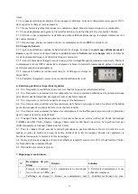
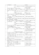
Страница 26: ...crous sont correctement serr s 6 2 Une fois par mois examiner tous les composants les roues le syst me hydraulique et la pompe lectrique pour d tecter des d formations des signes d usure et des bruit...

Страница 27: ...ontr ler les bornes et le com mutateur 3 Charger la batterie 6 Lorsqu on appuie sur la touche LOWER la fourche ne descend pas 1 Le commutateur ne fonctionne pas 2 Fusible d fectueux 3 Contacteur lectr...

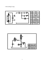
Страница 28: ...27 8 Plan de c blage lectrique 9 Plan hydraulique...

Страница 29: ...eur du chargeur Switch Interrupteur LIFT Button Touche LEVAGE LOWER Button Touche ABAISSEMENT Magnetvalve lectrovanne Coulometer Affichage de charge Hydraulic Cylinder V rin hydraulique Speed Control...

Страница 30: ...spondent aux exigences fonda mentales y relatives de s curit et de sant des directives CE La conformit n est plus valide pour une modification de la machine effectu e sans notre accord D signation des...

Страница 31: ...30...

Страница 32: ...31 K532 959 G 951 901...

Страница 33: ...os componentes principales de la serie EZ2515 34 Chasis 35 Cilindro hidr ulico 36 Portahorquillas 37 Horquilla ajustable 38 Rueda delantera 39 Rueda giratoria 40 Contrapeso 41 Caja el ctrica 42 Interr...

Страница 34: ...m x mm 1400 Longitud de horquilla mm 550 Anchura de horquilla mm 215 550 Anchura de horquilla individual mm 100 Di metro de rueda delantera mm 150 Di metro de rueda giratoria mm 150 Potencia del moto...

Страница 35: ...l ctrica antes de poner en marcha la carretilla elevadora 4 Controles previos a la puesta en marcha El funcionamiento correcto de la carretilla elevadora ya se comprob antes de embalarla Antes de la p...

Страница 36: ...riesgo de que el motor se sobrecaliente 5 1 8 Durante los desplazamientos de la carretilla elevadora la distancia entre el suelo y la horquilla debe ser de al menos 200 mm 5 1 9 Para no poner en riesg...

Страница 37: ...ctrica y retirar el pasador de la parte inferior del platillo de la v lvula A continuaci n extraer tambi n el pasador de conexi n entre el motor y el platillo de la v lvula 6 8 Limpiar el platillo de...

Страница 38: ...se necesario sustituirlo 4 Retirar los objetos extra os 7 El indicador de car ga no muestra nada o el indicador lumi noso rojo parpadea o la potencia de la bater a no es sufi ciente 1 Bornes e interru...

Страница 39: ...Charger Socket Conector del cargador Switch Interruptor LIFT Button Tecla ELEVAR LOWER Button Tecla BAJAR Magnetvalve V lvula magn tica Coulometer Indicador de carga Hydraulic Cylinder Cilindro hidr u...

Страница 40: ...construcci n y tipo de construcci n as como en el modelo que ponemos en circulaci n En el caso de que se modifique la m quina sin nuestro conocimiento esta declaraci n pierde su validez Denominaci n d...

Страница 41: ...40...

Отзывы: