background image

SDP650 – USER MANUAL 

TNM-U-E-0115 

Jun 15 (Iss. 1.4) 

Page 36 

MENU SCREENS


Use  the  ▼  and  ▲  keys  to  choose  the  required  contrast  level.    Press  the  F1  key  to  save  the 
selected contrast level and return to the main default screen. 

6.12


A

LERT 

V

OLUME 

M

ENU


This menu  allows  the  user  to  set the  offset  of the  Alert  Volume  in  relation  to  the current  Volume 
setting.  Thus, the alert tones can be made louder or softer than the main voice audio. 

Figure 24.  Alert Volume Menu screen. 

The level can be set in 33 steps over the range 0 to 32, with 0 (zero) being about the same as the 
voice level. 

Use the ▼ and ▲ keys to select the relative alert volume level.  A beep will sound at the indicated 
level each time the setting is changed. 

To acce

pt and save the setting and return to the previous screen, press the F1’ key. 

Note. 

A minimum Alert Level may be set by the FPP to ensure that the Alerts can always be 
heard from the speaker. 

6.13


S

PEAKER 

V

OLUME 

M

ENU


This  menu  allows  the  User  to  set  the  start-u

p  value  of  the  radio’s  audio  volume  control  for  user 

comfort. 

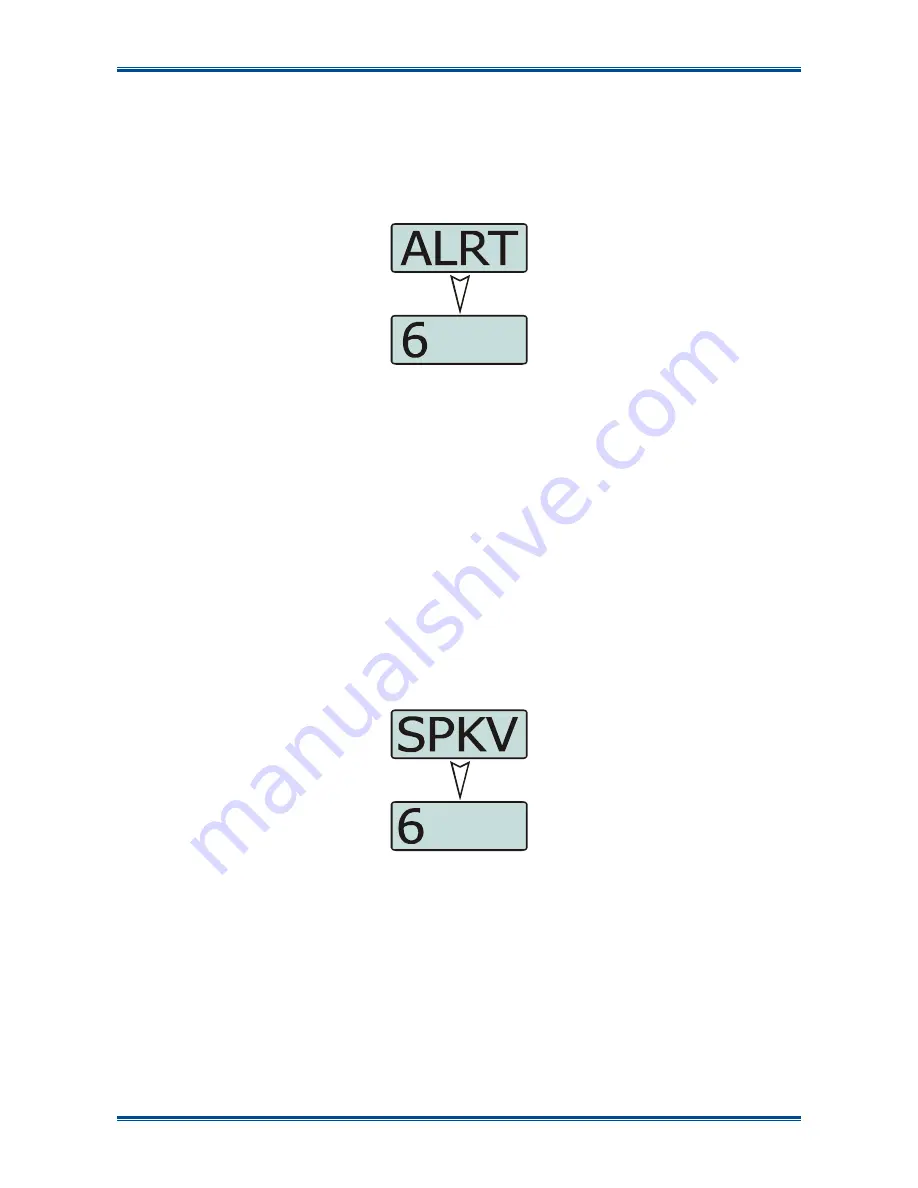
Figure 25  Speaker Volume Menu. 

The level can be set  in  33 steps over  the range 0 to 32, with 0 (zero) delivering no sound, 16 is 
normal level and 32 giving the maximum possible output from the speaker. 

Use  the  ▼  and  ▲  keys  to  select  the  relative  speaker  volume  level.    A  beep  will  sound  at  the 
indicated level each time the setting is changed. 

To accept and save the setting and return to the previous screen, press the F1 key. 

6.14


K

EY 

B

EEPS


The  Key  Beeps  menu  allows  the  User  to  enable  or  disable  the  acoustic  feedback  signals 
associated with pressing the function keys on the control unit. 

Содержание SDP650

Страница 1: ...June 2015 Field House Uttoxeter Old Road Derby DE1 1NH Tel 44 0 1332 375500 FAX 44 0 1332 375501 http www simocogroup com 1270 Ferntree Gully Road Scoresby Victoria 3179 Australia Tel 61 0 3 9730 3999 FAX 61 0 3 9730 3988 http www simocogroup com Simoco 2015 ...

Страница 2: ...ights including patent rights copyrights and trade secrets of Digital Voice Systems Inc This voice coding Technology is licensed solely for use within this Communications Equipment The user of this Technology is explicitly prohibited from attempting to extract remove decompile reverse engineer or disassemble the Object Code or in any other way convert the Object Code into a human readable form U S...

Страница 3: ...Initial Issue 1 1 July 2013 Additional General Precaution added plus changes to Support page email addresses 1 2 August 2013 1 3 October 2013 Details of Technical Support Ticket System added to Support page 1 4 9 June 2015 FCC Part 15 Compliance added to WARNINGS page plus changes to RF Exposure Compliance Distances for Bodyworn applications Table 1 Details of Duplex Operation included Section 4 9...

Страница 4: ...TED 18 2 1 PREPARING THE RADIO FOR USE 18 2 1 1 Charging the Battery 18 2 1 1 1 Procedure 18 2 1 2 Fitting the Battery 19 2 1 3 Fitting the Antenna 19 2 1 4 Fitting the Belt Clip 20 2 1 5 Fitting Audio Accessory Programming Cable 20 2 2 CONFIGURATION 20 3 FRONT PANEL CONTROLS 21 4 FUNCTIONS AND FACILITIES 23 DISPLAY 23 4 1 SWITCH ON SWITCH OFF 23 4 2 ADJUSTING THE VOLUME 23 4 3 SELECTING A ZONE 24...

Страница 5: ...ADJUST MENU 32 6 6 CONTACT MENU 33 6 7 RADIO INFORMATION 34 6 8 RSSI MENU 34 6 9 CALL LOG 34 6 10 SCAN MENU 35 6 11 CONTRAST MENU 35 6 12 ALERT VOLUME MENU 36 6 13 SPEAKER VOLUME MENU 36 6 14 KEY BEEPS 36 6 15 BACKLIGHT 37 6 16 BRIGHTNESS MENU 37 7 SPECIAL FUNCTIONS 39 7 1 CHANNEL UP AND DOWN 39 7 2 ZONE UP AND DOWN 39 7 3 SCAN ON OFF 39 7 4 SKIP 39 7 5 TALK AROUND ON OFF 39 7 6 LOW POWER 39 7 7 G...

Страница 6: ...re 14 Setup Menu 32 Figure 15 User Options Menu 32 Figure 16 Mute Adjust screen 33 Figure 17 Contact Menu screen 33 Figure 18 Radio Information Menu 34 Figure 19 Radio Information screens 34 Figure 20 RSSI Menu 34 Figure 21 Call Log Menu screen 35 Figure 22 Scan Menu 35 Figure 23 Contrast Menu screen 35 Figure 24 Alert Volume Menu screen 36 Figure 25 Speaker Volume Menu 36 Figure 26 Key Beeps Menu...

Страница 7: ...out a hands free kit whilst driving a vehicle Do NOT operate your radio in an explosive atmosphere unless the radio s level of IECEx approval is approved for use in that atmosphere Obey the Turn Off Two way Radios signs where these are posted e g on a petrol station forecourt Do NOT touch the antenna while the radio is transmitting Do NOT use or store the batteries above 60 C Do NOT dispose of bat...

Страница 8: ...Electrical Safety Regulations appropriate to the country of operation WARNING DANGEROUS VOLTAGES DANGEROUS VOLTAGES EXIST IN ALL THE BATTERY CHARGERS USED WITH THIS RADIO FOR THE APPROPRIATE SAFETY PRECAUTIONS REFER TO THE RELEVANT ELECTRICAL SAFETY REGULATIONS APPROPRIATE TO THE COUNTRY OF OPERATION HINTS FOR USING THE RADIO When transmitting hold the radio a few centimetres from your mouth and s...

Страница 9: ...s of protection All Simoco two way radios are designed manufactured and tested to ensure they meet government established RF exposure levels In addition manufacturers also recommend specific operating instructions to users of two way radios These instructions are important because they inform users about RF energy exposure and provide simple procedures on how to control it Please refer to the foll...

Страница 10: ...er accessories may not ensure compliance with the FCC s RF exposure guidelines and may violate FCC regulations Do not use this device if the operational requirements described herein are not met Instructions The radio transmitter power output is 5 Watts for PTT controlled held to face or bodyworn applications in analogue systems or for DMR systems 5 Watts burst power For radios enabled for held to...

Страница 11: ... Ear Approved Accessories This radio meets the FCC RF exposure guidelines when used with the Simoco accessories supplied or designated for the product Use of other accessories may not ensure compliance with the FCCs RF exposure guidelines and may violate FCC regulations To obtain a list of Simoco approved accessories please see the Simoco Group Departmental contact details on the Support page and ...

Страница 12: ...l Functions and Accessories Details of both the default and optional system configurations have been included in this User Manual therefore some material may not be relevant to every system Configuration is dependent upon the specification by the customer when the equipment was ordered and installed PAGINATION This manual is divided into a number of sections each section deals with one aspect of t...

Страница 13: ... US Customer Services Email customerservice simocogroup com TECHNICAL SUPPORT In order to streamline support requests and better serve our customers at Simoco we utilize a support ticket system Every support request is assigned a unique ticket number which customers can use to track the progress and responses online For reference Simoco provide complete archives and history of all customer support...

Страница 14: ...oco EMEA techsupport simocogroup com Simoco Australasia inquiry aus simocogroup com Simoco Americas techsupport simocogroup com Technical Support Helplines Simoco EMEA Tel UK 08717 411 040 International 44 0 1332 375 671 Simoco Australasia Tel Within Australia 1300 363 607 International 61 3 9730 3999 ...

Страница 15: ...ssion FDMA Frequency Division Multiple Access FOACSU Full Off Air Call Set Up FPP Field Personality Programmer GPS Global Positioning System ICNIRP International Commission on Non Ionizing Radiation Protection ID Identification IECEx International Electrotechnical Commission system for the certification to standards for electrical equipment for Explosives atmospheres IEEE Institute of Electrical a...

Страница 16: ...dio Receive Any DMR signal regardless of Colour Code or TGID will be heard Normal Mute Mode of Radio Receive Only signals with matching Colour Code will be heard Push To Talk The action or signal that causes the equipment to be placed into transmit mode or to be keyed Radio Unit ID Unique identifier allocated to each radio range 0 16 000 000 Scanning A process of selecting the first found permitte...

Страница 17: ... using the Field Personality Programmer FPP The configuration process loads the customised channels signalling and user options so that the radio will operate with the user s system 1 3 FEATURES The SDP650 portable radio has the following features Integrated Man Down motion and positional sensor for full employee safety IP67 performance for best in class resistance to water and dust Ear piece spea...

Страница 18: ...FER TO THE PERSONAL SAFETY PAGES The SRP650 radio is powered by a 2200 mAh Lithium Ion battery To avoid damage and comply with warranty terms the battery should be charged with a Simoco Standard Battery charger For best performance new batteries should be charged for 5 hours before initial use 2 1 1 1 Procedure This charging procedure assumes that the PAR 600CRG1 Single Rapid Charger is used For f...

Страница 19: ...o See arrow 1 in Figure 1 below Press down slightly on the battery release clip located at the top of the battery until a click is heard See arrow 2 Figure 1 Fitting the Battery To remove the battery turn the radio off Slide the battery release clip downwards to release the battery 2 1 3 Fitting the Antenna With the radio turned off locate the antenna in its threaded socket and turn clockwise to t...

Страница 20: ...ve the accessory socket cover 2 On the audio accessory programming cable locate the tab lug of the connector into either the top or bottom tab hole on the side of the radio as required see Figure 4 below 3 Tighten the screw to secure the audio accessory programming cable to the radio Figure 4 Fitting Audio Accessory Programming Cable 2 2 CONFIGURATION Before the SDP650 radio can be used it must be...

Страница 21: ...on buttons also have a second function provided by a longer button press Multi coloured LED for a clear indication of radio status Simple display for easy four character channel identification The Controls of the SDP650 Portable radio are shown below in Figures 5 Figure 5 SDP650 Controls The functions of each of the controls are detailed overleaf in Table 4 Nav Up Nav Down 1 2 3 4 5 6 7 8 9 10 11 ...

Страница 22: ...PTT switch to listen 8 Function Key F13 Prog function key Allows multifunction knob to select channel if held down 9 Display 10 Function Key F1 Prog function key Default Menu Select 11 Function Key F11 Prog function key Default Start Call 12 Function Key F12 Prog function key Default End Call Cancel power On Off 13 Function Key F4 Prog function key Default Back 14 Nav Up F7 Prog function key Defau...

Страница 23: ...he radio ON The display will illuminate and briefly show an Opening Message arranged by your dealer and the Selcall Identity of the radio if used After a brief time the display will show the selected channel see Figure 7 below at which time the radio is ready for use Figure 7 Typical display sequence after Switch On Pressing and holding the On Off button for approximately 2 seconds will switch the...

Страница 24: ...ted by pressing the Channel Up or Channel Down function keys when these have been programmed 4 5 MAKING A CALL TRANSMITTING Select the Zone Channel required on which to make the call To avoid interfering with other users of the channel listen first to ensure no transmissions are occurring To transmit to the selected channel s default radio talk group hold the radio or microphone about 10 cm in fro...

Страница 25: ...hin the preset time period to call back 4 6 1 Received Individual Calls Unanswered received Individual calls addressed to the radio are stored in radio memory The caller UID may be viewed answered and deleted by the user as desired A newly received individual call addressed to the radio sounds an alert tone periodically until the user presses any key If the caller UID of a newly received unanswere...

Страница 26: ...rom the Main Channel Screen to enter Scan Mode or select a channel that has been programmed as a scan channel Once selected the scanning will either start automatically if programmed or the programmed scan function button will need to be pressed FPP configurable While listening on the channel the user is able to PTT on that channel After the signal disappears the radio will remain listening on the...

Страница 27: ...stems branch of the navigation tree ensure that the Outgoing Telephony Calls are Duplex checkbox is selected See Figure 8 below Figure 8 Duplex Setup in FPP 4 9 3 Receiving Duplex Calls on the SDP650 In a Full Off Air Call Set Up FOACSU system the radio will start ringing Calls can be answered by pressing either the PTT button or the green connect button For Off Air Call Set Up OACSU systems the r...

Страница 28: ...ically transmitting continuously and will allow users to PTT to enable the microphone for each transmission See Figure 9 below Figure 9 FPP PTT TX Control for Duplex Call If the PABX caller is experiencing any audible feedback or echo in the FPP under the Global Audio section reduce the Earpiece Volume Offset and Mic Gain settings See Figure 10 below Figure 10 FPP Earpiece Volume and Mic Gain sett...

Страница 29: ...s often accessed Contact Radio Info Mute Adjust User Options Settings Backlight Brightness Contrast Key Beeps Speaker Volume Alert Volume Radio Status Help Display Test Test Mode Text Message Call Log The presence and order of the above menu selections is determined by the FPP configuration The Settings menu is a special case entry Settings is a subgroup that can have any of the list of menu selec...

Страница 30: ...e decrease a value Figure 11 Menu Navigation Example Select Zone Select Back Menu ENTRY POINT Default Screen Normal Channel Screen Channel Back Back Back Back Back Back Back Back Back Back Back Back Back Back Back Back Back Back Back Back Menu 1 Zone Select Note Example menus only shown Other Menus may be configured with the FPP Submenu Submenu Submenu Submenu Submenu Submenu Key Beeps ON OFF Back...

Страница 31: ...quired menu option is displayed and then press the F1 button Pressing the F4 key at any point will go back to the previous screen 6 1 CHANNEL MENU The Channel menu allows the user to select the communication channel to be used within a Zone Figure 12 Channel Menu The Channel Screen shows the currently selected channel Use the and keys to scroll through the other available channels and press the F1...

Страница 32: ...example Radio Info Radio software and hardware information RSSI Received Signal Strength Indication Test Mode Mute Adjust or Help 6 4 USER OPTIONS MENU The User Options menu allows the user access to a preset selection of menu options for user radio interface configuration items These include the backlight timeout period the backlight brightness the display contrast speaker and alert tone volume c...

Страница 33: ...ey to save the selected mute setting and return to the previous screen Direct access to the Mute Adjust screen from other screens can also be programmed to one of the function buttons with the FPP 6 6 CONTACT MENU The Contact Menu allows user to select the communication entity they wish to call e g individual radio unit UID or SUID talk group of radio units TGID dialled external network access gat...

Страница 34: ...t Figure 18 Radio Information Menu Press the F1 key to display the specific information screen Press the F4 key to return to the next highest menu level Figure 19 Radio Information screens 6 8 RSSI MENU The RSSI menu displays the signal strength of the received RF signal The current display is in dBm re 50 Ω and 1 mW and the reading is typically accurate to within 2 dBm Figure 20 RSSI Menu A lower...

Страница 35: ...ill place a call to the selected contact To return to the previous Menu level press the F4 key 6 10 SCAN MENU The Scan menu allows the User to manually start and stop the channel scanning process on the current channel if the channel is programmed as a scan channel in the FPP This Scan function can be programmed to a toggle key Figure 22 Scan Menu Use the and keys to select either the scan On or O...

Страница 36: ... accept and save the setting and return to the previous screen press the F1 key Note A minimum Alert Level may be set by the FPP to ensure that the Alerts can always be heard from the speaker 6 13 SPEAKER VOLUME MENU This menu allows the User to set the start up value of the radio s audio volume control for user comfort Figure 25 Speaker Volume Menu The level can be set in 33 steps over the range ...

Страница 37: ... for the set period after which the backlight will turn off The maximum backlight timeout period is programmed by the FPP The numerical values on the display are in seconds The choices available for the backlight timeout period are Always Off Always On 2 5 10 and 20 secs Figure 27 Backlight Menu screen Note Received radio traffic events will not prevent the backlight timeout Use the and keys to se...

Страница 38: ...50 USER MANUAL TNM U E 0115 Jun 15 Iss 1 4 Page 38 MENU SCREENS Use the and keys to select the required brightness level To accept and save the setting and return to the main default screen press the F1 key ...

Страница 39: ...hannel so the user can talk directly to other mobiles on the channel while the repeater is out of service or out of range When the key is pressed again or the Channel is changed the mobile s Tx channel reverts to its normal setting Talk Around mode is indicating to the user by a double beep at the start of each PTT 7 6 LOW POWER The Low Power function key forces the radio to low power Pressing the...

Страница 40: ...Status using a programmed Man Down button see buttons The Man Down system sequence is The radio s man down system is enabled by pressing the allocated Man Down button The radio uses a 3D accelerometer to determine the direction of the gravity s 1 g downward acceleration The direction of this force is averaged during the learning time Once trained the gravity component of the acceleration is remove...

Страница 41: ...SDP650 USER MANUAL TNM U E 0115 Jun 15 Iss 1 4 Page 41 SPECIAL FUNCTIONS The Lone Worker countdown is reset after any user activity with the radio i e either PTT or Lone Worker buttons are pressed ...

Страница 42: ...rger PSU SA 230 V AC with 3 pin SA fitting PA PSU1A5 SDP Single Charger PSU Excludes Mains Cord PA ACCORD XX8 PAR 600CRG2 SDP Dual Charger Unit Excludes Power Supply PA PSU3A0 Charger for two portable radios PA PSU 3A5 SDP Dual Charger PSU PA ACCORD UK8 UK Mains Cord for PA PSU3A0 IEC C7 to UK 3 Pin 1 8 m PA ACCORD EU8 EU Mains Cord for PA PSU3A0 IEC C7 to Euro 2 Pin 1 8 m PA ACCORD SA8 SA Mains C...

Страница 43: ...SDP650 USER MANUAL TNM U E 0115 Jun 15 Iss 1 4 Page 43 ACCESSORIES Part No Description Notes SA 600IMD Intelligent Man Down License SA 600MST Multi Site Trunking License Available Q2 2013 ...

Страница 44: ...er Off Complete 880 Hz 1 sec Alert tone generated after radio saves its data and is ready to power down PTT Grant 1000 Hz 30 ms Generated after PTT request granted and radio starts transmitting Call Alert 2000 Hz 100 ms x5 When receiving a message Emergency 600 Hz 160 ms 1800 Hz 100 ms Generate a short confidence beep when alarm mode is activated This short beep can be enabled disabled in FPP Man ...

Страница 45: ...SIMOCO GROUP Global Headquarters Field House Uttoxeter Old Road Derby DE1 1NH UK Tel 08717 411 050 Fax 08717 411 049 International Tel 44 0 1332 375 671 Fax 44 0 1332 375 672 www simocogroup com ...

Отзывы: