In these cases, when assembling, recover the silicone gasket
used on the terminal adapter (5 fig. 17), which is to be
replaced by the doubler, and insert it into the seat made in the
doubler.
For this type of discharge the sum of the maximum
rectilinear development allowed for the pipes must not
exceed 7.00 mm H
2
O (“80 - 80 E” models) and 11.00 mm
H
2
O (“100 E” model).
When calculating the lengths of pipe,
take into account the parameters given in the
Table 2.
3.7
WATER CONNECTIONS
3.7.1
Central heating connections
– Fit the two C.H. isolation valves using the gaskets supplied
to the flow and return connections as shown in fig. 2. The
pipe connections are labelled on the lower part of the boiler.
– Connect the C.H. pipework as required.
3.7.2
D.H.W. connections
– Fit the D.H.W. isolation valve to the cold water inlet con-
nection as shown in fig. 2.
– Fit the union connection to the D.H.W. outlet.
– Connect the D.H.W. pipework as required.
3.8
GAS CONNECTIONS
– Screw the gas cock into the internal thread in the gas
inlet connection using a suitable jointing compound.
– Connect the gas supply pipe.
3.9
SAFETY VALVE CONNECTION
– The appliance safety valve is located towards the R.H.S. of
the boiler and the discharge pipe is supplied loose.
Remove the two selftapping screws and lower the control
box to improve access.
– Screw the discharge pipe to the valve outlet using a suit-
able jointing compound, and extend the pipe to ensure
that any discharge from the safety valve is safely routed
to a drain. The discharge pipe should be a minimum of 15
mm copper, and should avoid sharp corners or upward
pipe runs where water may be retained.
3.10
WIRING INSTRUCTIONS
(Refer to sections 2.6 - 2.7 and fig. 19)
The external wiring is connected to the boiler via a lead cable
situated behind the control box at the L.H.S.
– If a room thermostat is to be used, unscrew the two
screws at either side of the control box, pivot the box
downwards, then remove the room thermostat connec-
tion cover (one screw) to gain access to connector TA.
– Remove the pre-wired kink and connect the room thermo-
stat to terminals 22 and 23.
– Re-fit the room thermostat connection cover.
The thermostat or timer-thermostat, recommended for
better room temperature control, must be class II as
specified by standard EN 60730.1 (clean contact).
– Carry out electrical system checks through a suitable test
meter: earth continuity, polarity, resistance to earth and
short circuit.
– Re-secure control box.
13
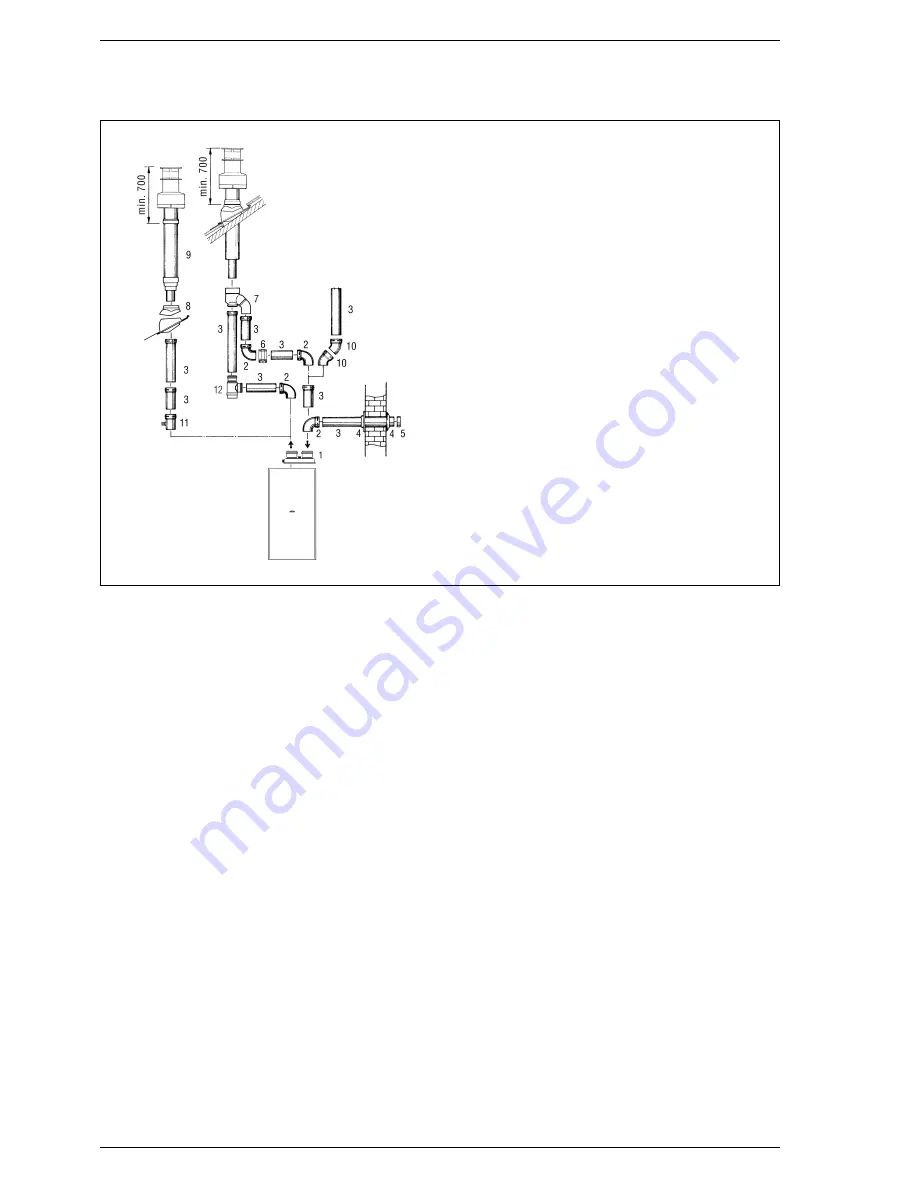
Fig. 18
KEY
1
Air-smokes flow splitting unit
with take-off point
code 8093000
2 a 90° elbow MF
code 8077404
2 b Isolated 90° elbows MF
code 8077408
3 a Extension L. 1000
code 8077303
3 b Isolated extension L. 1000
code 8077306
4
Int.-est. ring kit
code 8091500
5
Intake terminal
code 8089500
6
Locking junction (n. 5)
code 8092700
7
Doubler fitting
code 8091400
8
Tile with articualted joint
code 8091300
9
Roof outlet terminal L. 1240
code 8091201
10
45° elbow MF
code 8077406
11
Condensation outlet L. 135
code 8092800
12
Tee condensation outlet
code 8093300
Содержание benchmark FRIENDLY FORMAT
Страница 1: ...Friendly Format Installation and servicing instructions GB ...
Страница 33: ...Friendly Format User instructions GB ...
Страница 34: ......
Страница 39: ......


