


09
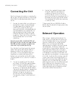
Rear Panel Layout
Figure 1: 870A Rear panel
When you’re using the balanced XLR inputs, you
must first remove the factory installed “dummy”
XLR jumpers (see figure 2 below) from the back
panel XLR connectors and store them in a safe
place. These jumpers are required ONLY when
using the single-ended RCA inputs. If you decide
to switch to single-ended input mode, you must
reinstall the XLR jumpers (between pins 1 and 3)
exactly as show below:
There are two pairs of heavy duty gold-plated
speaker binding posts for each channel to
accommodate bi-wiring. They are each labelled
“Right Speaker Out” and “Left Speaker Out”.
The lower left section has an RS-232 input on a
DB9 connector. To the right of this connector are
two 12 Volt triggers, each on a 1/8” mini-jack;
one input and one output, the latter for use in
the event that wish you to “daisy chain” a second
power amplifier on the same trigger circuit. The
lower right section has from left to right; the “AC
Fuse” socket cover; the power “main switch”;
and the “AC Input” IEC receptacle for the power
cord.
The rear panel will look similar to Figure 1 (above). Each channel has one balanced (differential) input on an
XLR connector and one unbalanced (single-ended) input on a RCA connector. There is no switch to toggle
from balanced mode to single-ended mode. You may operate the amplifier in either mode, but only one mode
at one time for each channel.
Figure 2: XLR connector without
and with jumper accessory
Содержание MOON 870A
Страница 1: ...The performance of a lifetime Owner s Manual MOON 870A Power Amplifier...
Страница 7: ...05...
Страница 9: ...07...
Страница 18: ...Simaudio Ltd 1345 Newton Rd Boucherville Quebec J4B 5H2 CANADA T 450 449 2212...


