SAFETY INSTRUCTIONS
It is important to read and understand your instruction manual.
Learn the tools application, as well as it's limitations and the
potential hazards associated with this tool.
ADDITIONAL SAFETY INSTRUCTIONS FOR MULTIMETER
• This meter is designed according to IEC-1010 with an over-
voltage category (CAT III) and pollution 2.
• Follow all safety and operating instructions to ensure that
the meter is used safely and is kept in good operating
condition.
• Safety Symbols:
Important safety information, refer to the operating manual.
Dangerous voltage maybe present.
• Double insulation (Protection Class III).
• This meter is safe only according to standard procedures
when used in conjunctions with the supplied test leads.
Replace damaged test leads only with the same model or
same electric specifications.
• Do not use the meter before the cover is in place to avoid
risk of electric shock.
• The range switch should be in the right position for testing.
• To avoid electric shock and damaging the instrument, the input
signals should not exceed the specified limits.
• When measuring switched power such as TV sets, attention
should be paid to the possible pulses that may cause
destruction of the circuit.
• Range switch position should never be changed at random
during measurement.
• Caution against shock when measuring voltages higher
than DC 60V & AC 30V.
• Protection fuse should be replaced only with same type and
specification.
1. Function And Range Switch
This switch is used to select the function and desired range as
well as to turn on the instrument.
To extend battery life, the switch should be in the "OFF"
position when the instrument is not in use.
2. Display
31/
2
digit, 7 segment, 12.50mm high LCD.
3. "10A" Jack
Plug in connector for red (positive) test lead for 10A
measurement.
4. "VΩmA" Jack
Plug in connector for red (positive) test lead for all voltage and
resistance and current (except 10A) measurements.
5. "Common" Jack
Plug in connector for black (negative) test lead.
SPECIFICATIONS
Accuracies are guaranteed for 1 year, 23˚C +/- 5˚C, less than
75% relative humidity.
DC Voltage
INPUT IMPEDANCE: 1M ohm
AC Voltage
RESPONSE: Average responding, calibrated in rms of a sine
wave.
FREQUENCY RANGE: 45Hz-450Hz
DC Current
OVERLOAD PROTECTION: 250mA/250V fuse (10A range
unfused).
Resistance
MAXIMUM OPEN CIRCUIT VOLTAGE: 2.8V
Audible Continuity Test And Diode
DCV
ACV
DCA
DIGITAL
MULTIMETER
200
20
2000m
200m
2000k
200k
20k
2000
200
10ADC
10Amax
750VAC
1000VDC
200mAmax
COM
500Vmax
CATII
PNP
NPN
E
E
C
B
E
E
B
C
hFE
V mA
10A
1000
OFF
750
200
2000
20m
200m
200
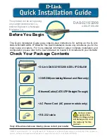
Product Familiarisation
Digital Multimeter
2
1
3
4
3
5
Transistor hFE Measurement
Temperature Measurement (K Type Probe)
PRIOR TO USE
Thoroughly read and understand the operating instructions
before proceeding further. Attention before operation.
WARNING
1. To avoid electrical shock hazard and/or damage of the
instrument, do not measure voltages that might exceed
500V above earth ground.
2. Before the use of instrument, inspect test leads, connectors
and probes for cracks, breaks or crazes in the insulation. If
any damage is present do not use the instrument.
3. The range switch should be positioned to the desired
measurement range before operation.
OPERATING INSTRUCTIONS
DC Voltage Measurement
1. Connect red test lead to"VΩmA" jack. Black lead to "COM"
jack.
2. Set RANGE switch to desired DCV position. If the voltage to
be measured is not known beforehand, set switch to the
highest range and reduce it until satisfactory reading is
obtained.
3. Connect test leads to device or circuit being measured.
4. Turn on power of the device or circuit being measured, voltage
value will appear on digital display along with the voltage
polarity. * In DCV 1000 position the "HV" will appear on digital
display.
AC Voltage Measurement
1. Connect red lead to "VΩmA" jack. Connect black lead to
"COM" jack.
2. Set RANGE switch to desired ACV position.
3. Connect test leads to device or circuit being tested.
4. Read voltage value on digital display.
*In ACV 750 position the "HV" will appear on digital display.
DC Current Measurement
1. Connect red lead to "VΩmA" jack. Connect black lead to
"COM" jack. (For measurements between 200mA and 10A
connect red lead to "10A" jack with fully depressed).
2. Set RANGE switch to desired DCA position.
3. Open the circuit to be measured, and connect test leads
IN SERIES with the load in which current is to be measured.
4. Read current value on digital display.
*In 10A range, measure time can't exceed 15 second.
Resistance Measurement
1. Connect red lead to "VΩmA" jack. Connect black lead to
"COM" jack.
2. Set RANGE switch to desired Ω position.
3. If the resistance being measured is connected to a circuit,
turn off power and discharge all capacitors before
measurement.
4. Connect test leads to circuit being measured.
5. Read resistance value on digital display.
Diode Measurement
1. Connect red lead to "VΩmA" jack. Connect black lead to
"COM" jack.
2. Set RANGE switch to position.
3. Connect the red test lead to the anode of the diode to be
measured and black test to cathode.
4. The forward drop in mV will be displayed. If the diode is
reversed, figure "1" will be shown.
Transistor hFE Measurement
1. Set RANGE switch to the hFE position
2. Determine whether the transistor is NPN or PNP type and
locate the emitter, base and collector leads. Insert the leads
into the proper holes of the hFE socket on the front panel.
3. The meter will display the approximate hFE value at the
condition of base current 10uA and Vce 2.8V.
Temperature Measurement
1. Connect the K type, thermoelectric couple to "VΩmA" and
"COM" jacks.
2. Set RANGE switch to TEMP˚C position.
3. The display will read the temperature value ˚C
Audible Continuity Test
1. Connect red lead to "VΩmA". Connect black lead to "COM".
2. Set RANGE switch to position.
3. Connect test lead to the points of circuit to be tested. If the
resistance is lower than 100 ohm, buzzer will sound.
Test Signal Use
1. Set RANGE switch to position.
2. A test signal appears between "VΩmA" and "COM jacks.
The output voltage is approx 5V p-p with 50k ohm
impedance.
MAINTENANCE
• Fuses rarely need replacement and blow almost always as
a result of operator error. If " " appears on the display, it
-indicates that the battery needs replacing
• Before attempting to remove the battery door or open the
case, be sure that test leads have been disconnected from
measurement circuit to avoid electric shock hazard.
• To avoid electrical shock, remove test leads from measurement
circuits before replacing the fuse. Replace fuses only with a
specified rating: F-200mA/250V fuse.
• Replace the test leads if the lead is damaged or exposed in
any way. Only replace leads with the same type and
specification.
• Use only moist fabric or small amount of detergent, never use
chemical solutions for cleaning.
• Do not use the meter before the back cover is properly closed
and screw secured.
• Upon any abnormality, stop operation immediately and send
the meter for maintenance by a qualified technician.
RANGE
200mV
2000mV
20V
200V
1000V
RESOLUTION
ACCURACY
100uV
1mV
10mV
100mV
1V
+0.8% of rdg +2Digits
RANGE
200V
750V
RESOLUTION
ACCURACY
100mV
1V
+1.2% of rdg +10Digits
RANGE
200uA
2000uA
20mA
200mA
10A
RESOLUTION
ACCURACY
100nA
1uA
10uA
100uA
10mA
+1.0% of rdg +2Digits
+1.2% of rdg +2Digits
+2.0% of rdg +5Digits
RANGE
200 Ω
2000 Ω
20K Ω
200K Ω
2000K Ω
RESOLUTION
ACCURACY
0.1 Ω
1 Ω
10 Ω
100 Ω
1K Ω
+1.0% of rdg +2Digits
RANGE
NPN/PNP
TEST
RANGE
Vce=2.8V
TEST
CURRENT
TEST
VOLTAGE
0-1000
Ib=10uA
RANGE
DESCRIPTION
The forward voltage drop in mV will be displayed.
(Test voltage: 2.8V)
Built - in buzzer sounds if resistance is less then
100 ohm
RANGE
-40˚C–+1000˚C
RESOLUTION
ACCURACY
1˚C
+3.0% of rdg +2D
589681-Instructions.indd 2
12/3/07 14:34:45