1-5-3
HE261DC
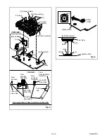
[6] Main CBA
(S-6)
(S-6)
(S-7)
[5] Deck Assembly
FE Head
Cylinder Assembly
AC Head
Assembly
TOP VIEW
From
FE Head
From
Cylinder
Assembly
From
AC Head
Assembly
Lead with
blue stripe
Lead with
blue stripe
Desolder
from bottom
Lead with
blue stripe
From
Capstan Motor
Assembly
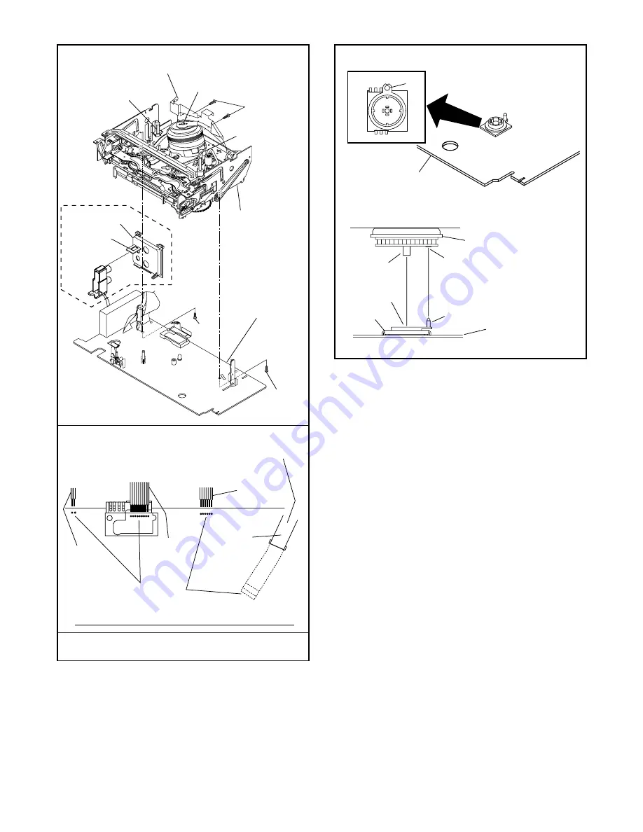
Lead connections of Deck Assembly and Main CBA
Printing
side
[7] Cylinder Shield
[8] Jack Board
(L-3)
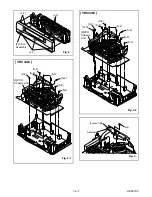
[ VRC4060 ]
Fig. 5
LD-SW
Pin
Hole
Hole
Shaft
Cam Gear
[6] Main CBA
[5] Deck Assembly
[6] Main CBA
SW507
LD-SW
Pin
Fig. 6
Содержание VRC4020
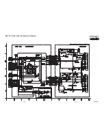
Страница 30: ...1 8 15 1 8 16 HE261SCM7 Main 7 7 Schematic Diagram...
Страница 34: ...1 8 23 1 8 24 Jack CBA Top View Jack CBA Bottom View BHE470F01014 C...
Страница 59: ...3 1 1 HE360_460FEX A1X EXPLODED VIEWS Front Panel...
Страница 61: ...3 1 3 HE261PEX Some Ref Numbers are not in sequence X2 X3 X20 X1 X4 S1 Unit S3 A14 S2 S2 Packing...
Страница 78: ...VRC4020 VRC4060 HE261 463ED...


