Copyright Donald W Thomas, K5ZRQ
10
7.0 ALIGNMENT:
ALIGNMENT – LA-550, LA-600, LA-650
This alignment procedure applies to the LA-550, LA-600, and LA-650 amplifiers.
1. Driver Neutralization
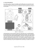
A. Connect RF Voltmeter to the cathodes of the four PA tubes. If a RF Voltmeter is not
available, an Oscilloscope with a bandwidth over 30 Mhz can be used with a 10X Probe.
B. With linear amplifier off, key your transmitter, depress relay K-1 with an insulated tool, and
adjust the neutralization trimmer (it is under the driver tube) for a dip or minimum
reading on the RF Voltmeter or Oscilloscope. The amplifier is now neutralized.
2. Bias (Driver)
A. Connect a DC Voltmeter to Pin 2 of the driver tube (the cathode).
B. Turn linear amplifier on, set to high power position.
C. Adjust bias pot (one closest to power supply) for a .5 VDC reading on Pin 2.
3. Bias (Power Amp)
A. Connect DC Voltmeter across the one ohm, 10 watt resistor in the cathode of the power amp.
B. Turn linear amplifier on, set to high power position.
C. Depress relay using insulated tool. Adjust power amplifier bias pot for a .05 reading on your
voltmeter.
4. Tune Up:
A. Adjust Driver Grid Tuning and Plate tune output capacitor for maximum power out.
B. Adjust power amplifier front panel Plate and Load for maximum power out.

