background image


SILTRONIX 


MODEL LA-600 RF Amplifier 


OPERATING/SERVICE MANUAL 


SILTRONIX 

330 VIA EL CENTRO 

OCEANSIDE, CALIFORNIA 92054 


Original manual print date unknown 

Copyright 2007 Donald W. Thomas, K5ZRQ 

Artwork and Diagrams by Bennie Bolin 

Содержание LA-600

Страница 1: ...ODEL LA 600 RF Amplifier OPERATING SERVICE MANUAL SILTRONIX 330 VIA EL CENTRO OCEANSIDE CALIFORNIA 92054 Original manual print date unknown Copyright 2007 Donald W Thomas K5ZRQ Artwork and Diagrams by Bennie Bolin ...

Страница 2: ...ears of trouble free service It is important however the Operating Instructions should be followed The RF drive requirements to the amplifier should not be exceeded Once the unit has been installed and tuned for proper operation retuning of the amplifier should not be required Even though the rugged 8950 s should provide years of trouble free operation the most severe conditions for the tubes exis...

Страница 3: ... modulation is present In AM position the AM carrier of the transmitter keeps the amplifier in the Transmit mode as long as the transmitter is keyed PI Output Circuit Matches 52 to 75 ohm load and other impedances where the SWR does not exceed 2 5 1 Pre Amplifier Provides approximately 6 db gain for received signals Power Supply Computer grade electrolytic capacitors and conservatively rated silic...

Страница 4: ...of the exciter or measure the power output with a wattmeter 3 Connect a short length of coaxial cable RG 58 or RG 8 from the exciter transceiver or transmitter to the INPUT jack on the rear of the LA 600 A PL 259 connector is required to connect the coax cable to the amplifier Coax cable should be as short as possible 4 Connect antenna or suitable high power dummy load to the OUTPUT connector on t...

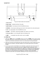
Страница 5: ...nput 4 DELAY SSB Position Allows the relay to remain in Transmit mode during short pauses while transmitting AM Position Continuously keeps the LA 600 in the transmit mode so long as the exciter is in transmit 5 PRE AMP OFF Position Exciter receives signal directly from antenna ON Position Exciter receives signal from PRE AMP which provides approximately 6 db gain The PRE AMP switch operates indep...

Страница 6: ...ustment to be made to the exciter before operating the LA 600 Use this setting for checking drive power 2 Initial tune up should be accomplished with the exciter transceiver set at the middle range of the frequencies to be operated This allows operation over the entire range without re tuning the amplifier 3 The tune up procedure should initially be accomplished by applying the exciter driving pow...

Страница 7: ...just PLATE control for maximum meter reading There should be a definite maximum meter reading and as the PLATE control is moved in either direction the reading should decrease 8 Quickly adjust the LOAD control for maximum meter reading 9 Steps 7 and 8 should be repeated several times until no greater reading can be obtained Do this as rapidly as possible 10 Now switch RF POWER switch to HIGH and r...

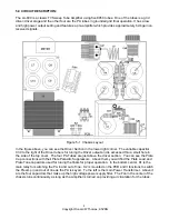
Страница 8: ...iver output and is accessed thru a small hole in the side of the top cover The four PA Tubes are just above the driver section You can see the Plate Cap connections with their Plate Parasitic Suppressors Above them you will find the Plate Load and Plate Tune capacitors used for tuning the finals for proper operation In the bottom center K1 is the main relay for switching the PA in and out of line ...

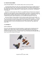
Страница 9: ...e LA 600 as indicated by the labeling Figure 6 1 PCB The wire connections to the PCB are as listed below 1 Wire from PCB to relay K2 NO contact 2 Connects to RF Input Jack 3 Connects to Delay switch SSB contact 4 Connects one end of R42 the other end of R42 is connected to the RF Output Jack 5 Connects to the front panel meter 6 Connects to Preamp switch 7 Connects to Preamp switch 8 Connects to t...

Страница 10: ...nimum reading on the RF Voltmeter or Oscilloscope The amplifier is now neutralized 2 Bias Driver A Connect a DC Voltmeter to Pin 2 of the driver tube the cathode B Turn linear amplifier on set to high power position C Adjust bias pot one closest to power supply for a 5 VDC reading on Pin 2 3 Bias Power Amp A Connect DC Voltmeter across the one ohm 10 watt resistor in the cathode of the power amp B...

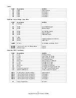
Страница 11: ...pF Mylar Driver Section C21 100uF 250VDC Electrolytic HV Section Bottom chassis term strip C22 002uF Ceramic Disc Driver socket pin 11 C23 002uF Ceramic Disc Driver socket pin 3 C24 002uF Ceramic Disc Driver socket pin 2 C25 3 3pF 3KV Ceramic Disc Driver Section C26 3 3pF 3KV Ceramic Disc Driver Section C27 002uF 2KV Ceramic Disc Driver Section C28 002uF 2KV Ceramic Disc Driver Section C29 270pF 2...

Страница 12: ...n R4 470K 1W HV Section R5 39K 6W DALE FP33 6W HV Section R6 39K 6W DALE FP33 6W HV Section R7 39K 6W DALE FP33 6W HV Section R8 39K 6W DALE FP33 6W HV Section R9 1K 1W Bias Power Supply R10 4 7K 1W VR1 and term strip R11 4 7K 1W Across VR1 R12 6 8K 1W Tied to VR1 R13 10K 1 2W Driver Section Bottom chassis term strip R14 12K 10W HV Section Bottom chassis term strip R15 10K 10W HV Section Bottom ch...

Страница 13: ...rminal Strip Potentiometers Ref Description NOTES VR1 5K Bottom Chassis VR2 25K Bottom Chassis VR3 10K On PCB Diodes Ref Description NOTES D1 1N4822 HV Section D2 1N4822 HV Section D3 1N4822 HV Section D4 1N4822 HV Section D5 1N4005 Bias Power Supply On Terminal Strip D6 1N4005 LV Power Supply On Terminal Strip D7 1N914 On PCB Keying detector D8 1N4005 Across K1 D9 1N914 On PCB D10 1N4005 On PCB A...

Страница 14: ...er 6 each Inductors RFC Transformer Ref Description NOTES L1 4 uH Filament Choke L2 17 uH Driver Plate HV Choke L3 55 uH Driver Plate HV Choke L4 55 uH PA Cathode Choke L5 Wire Coil Driver Section Pi Network L6 17 uH PA Plate HV Choke L7 55 uH PA Plate HV Choke L8 Wire Coil PA Section Pi Network L9 30 uH PA Section Mounted under C49 L10 Preamp Tuning Coil On PCB Tunes Preamp Input L11 GRID TUNING ...

Страница 15: ...r stage must be re aligned and re neutralized because the internal capacitances of the two different tube types are not the same Also when using the 10 lead transformer the two primary windings must be wired in parallel For the 110V AC source the 2 windings are 1 orange and brown and 2 yellow and green To wire them in the proper phase the orange and yellow leads are both connected to the unswitche...

Страница 16: ...sembly Put brass roller back into the housing and push it to the end with the side contacts Put the three piece part back in with the grooved guide end riding on the middle of the brass roller Place the two insulators back on the sides of the housing Move toggle on top cover to the side labeled ON While holding the housing and insulators together slide the top cover down over the housing The botto...

Страница 17: ...vered under the warranty policy for a period of 90 days This warranty is valid only if the enclosed card is properly filled out and mailed to the factory within ten days of purchase Do not ship equipment to the factory without prior authorization This warranty is limited to repairing or replacing only the defective parts and is not valid if the equipment has been tampered with misused or damaged A...

Отзывы: