background image

Attention: Under normal conditions, a photovoltaic module is likely
to experience conditions that produce more current and/or voltage
than reported at standard test conditions. Accordingly, the values
of ISC and VOC marked on this module should be multiplied by a
factor  of  1.25  when  determining  component  voltage  ratings,
conductor ampacities, fuse sizes, and size of controls connected
to the PV output.

Attention: Refer to Section 690-8 of the National Electrical Code
for an additional multiplying factor of 125 percent (80 percent
derating) which may be applicable.

For field connections, use minimum No. 10 AWG copper wires insulated
for a minimum of 194°F / 90 ºC.

Once the modules are connected in series to obtain the correct input
voltage for each type of inverter it is essential that protection fuses are
located between the inverter and each series. These fuses will facilitate
maintenance and control tasks, but they will mainly protect the series
from each other should the polarity of one of the series of modules be
incorrectly connected.

Series fuse (overcurrent protection) rating of 

15 

A.

Protection fuses

14

Instructions for using photovoltaic modules

!

!

Содержание Photovoltaic

Страница 1: ...use...

Страница 2: ...ort for our products n manual carefully in its entirely before handling the photovoltaic module P R O C E S S E D CHLO R I N E F R E E PCF Processed Chlorine Free Recycled Forestry Stewardship Council...

Страница 3: ...Table of contents ructions or use and guarantee cal hazards es y instructions ding nformity 3 4 6 8 10 13 14 16 20 22 33 35 41...

Страница 4: ...included in This symbol indicates that there is a personal safety ect both you and others and cause damage to the ty not contradict any regulation that could have changed publication date The last ver...

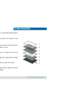
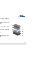
Страница 5: ...ass providing rigidity to the rface of the cells ction is to encapsulate the cell circuit olar cells These generate the electricity the rear surface of the module mple method of electrically connectin...

Страница 6: ...ised of the following ed glass providing rigidity to the unit the cells on is to encapsulate the cell circuit r cells These generate the electricity lass ple method of electrically connecting ation 5...

Страница 7: ...ower generation nt the active surface of the modules towards the ssible in the northern hemisphere and towards the ssible in the southern hemisphere tructure for the photovoltaic modules should be n t...

Страница 8: ...some of its components and ess as well as the electrical security odule with care even if it has the aluminium frame s or on a corner of the frame could deform it enough odify or adapt the PV module D...

Страница 9: ...iken has a series of rigorous quality controls phase of the production process along with a final output power for all manufactured modules Siliken ass modules are tested according to EN 14449 year gu...

Страница 10: ...77 F 36 F 1 5 Air mass STC 1000 Air mass and specified in the Siliken product s tion for 10 years rantees output power from the photovoltaic module minimum output power measured under standard 94 W ft...

Страница 11: ...rrent rrent consumer A cell exposed to solar radiation anging between 6 and 8 amps with a potential 0 6 volts However when a cell is partially shaded ee for example it starts to consume the electricit...

Страница 12: ...11 tion Operation with the cell in the shade...

Страница 13: ...hotovoltaic module s must remain disconnected es on the photovoltaic array thus guaranteeing that en In any event the decision to change the diodes f Siliken to use original spares or parts replaced b...

Страница 14: ...umber of ected in series in cell temperature conditions of ed in the electrical data tables of the modules data e for the maximum number of modules must be r location and in accordance with the correc...

Страница 15: ...ational Electrical Code multiplying factor of 125 percent 80 percent y be applicable use minimum No 10 AWG copper wires insulated 4 F 90 C re connected in series to obtain the correct input of inverte...

Страница 16: ...sities of the series of connected method indicated in the National Electrical Code s type of protection in the event of an incorrect polarity connection will cause the reversed series ity receiver cau...

Страница 17: ...Keep children away from the system during installation Do not carry out the installation components always use appropriate tools covered als It is recommended to avoid handling modules Before handling...

Страница 18: ...tection If ctly sealed there is a risk of damage to the module e terminals of the modules if they are electrically evices of the system Before loosening connectors les from the inverter or the battery...

Страница 19: ...nt present will be the nt from each module This means that an installation s may contain high levels of voltage and current ame of the module to the structure avoid rubbing sulation on the rear surfac...

Страница 20: ...ulations norms and prerequisites for buildings our local authorities Keep in mind that a roof top ation may affect the building s fire security erroneous dules can increase this risk in case of fire t...

Страница 21: ...and current behaviour of the cells r radiation and temperature Therefore the actual of a photovoltaic module will depend on the region nstalled and the ambient conditions in that region nce in relatio...

Страница 22: ...amps that of generating at 77 F 25 C the current increases ee centigrade of increase in the module temperature reases e a decrease of the photovoltaic module power as ture increases at a ratio of 0 43...

Страница 23: ...eaning that the photovoltaic module works allation must be designed according to the Building particular country in question ust be anchored in a secure manner using special embly sets for photovoltai...

Страница 24: ...ic rubber to avoid direct metal parts of the PV module and the supporting o prevent possible deformations of the parts that odule that the connection box cable holders are never he direction of the in...

Страница 25: ...o lation minimum of 50 mm 1 97 inches es that serve as a roof tile it must be assured that odules is ventilated ule is not a structural element Be sure that the o support any load that could cause the...

Страница 26: ...a ames are supplied with 4 holes on the aluminum es and with the diameters that are specified in the oducts available at www siliken com These holes he module to a structure which must have been ied t...

Страница 27: ...he perimeter such as those designed for integration on roofs or 5 mm must be left between modules in order to een them due to thermal expansion For less space bber gaskets that prevent contact must be...

Страница 28: ...e from contacting outside objects pecially when the module is under load The back maged ed below are only for standard modules without ed without the aluminum frame handle it as follows modules with e...

Страница 29: ...es to absorb ractions due to temperature changes laminate to the support structure do so using or clamps with a rubber gasket or similar devices minated modules without a frame To assure correct ent t...

Страница 30: ...tach the module around the perimeter such as those designed for integration on roofs or e details of where the anchor clamps should ach model of the modules mps should be placed on each lengthwise edg...

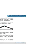
Страница 31: ...uld be placed on each lengthwise edge of n in the diagram below ed below are only for standard Glass Glass PV Mechanical assembly of the modules Instructions for using photovoltaic modules 310 80 80 3...

Страница 32: ...h profiles that are suitable for structural glass so ened by all four edges or by the two longest edges e details of where the anchor clamps should be model of the modules ps should be placed on each...

Страница 33: ...liken from any ty for damage to property or injury to people n that may need to be made to what is detailed e user manual contact Siliken Modules in order he possibility of allowing any such variation...

Страница 34: ...surface of the PV module with plenty of water at ature and at low pressure for approximately 3 zed water max of 100 bar can also be used from ess than 50 cm urface with a soft polyurethane sponge or...

Страница 35: ...sion glands ont face of the photovoltaic modules to verify that o perform the checks and minimum maintenance shed in these instructions will lead to the uarantees and the exoneration of SILIKEN for wh...

Страница 36: ...must be grounded during 690 43 and to accomplish this Siliken Modules e following components ess steel bolt with hexagonal nut ss steel serrated washers onnector for 10AWG cable with washer for M4 bol...

Страница 37: ...m possible electrical signals that are predictable oid high potential differences between the glass ame with respect to the negative of the module e the glass and encapsulating materials to become whi...

Страница 38: ...les provided on the modules s anodized so it is essential to remove the anodized the hole in the local area beneath the base of the nectivity between the ground lug and the module emery paper or an ab...

Страница 39: ...Grounding Lug Assembly e lied by the installer of the system Solklip Trademark Grounding Clip Assembly Module frame grounding Instructions for using photovoltaic modules...

Страница 40: ...the local area beneath the base of the nectivity between the ground lug and the module unding clip onto the frame making sure that the rilled hole thread the screw into the hole until the head is flu...

Страница 41: ...s it is advisable to protect lls from possible electrical signals that are le potential differences between the glass h respect to the negative of the module ss and encapsulating materials to become o...

Страница 42: ...ule ls SLK60P6L SLK36P6L SKL60M6L SLK36M6L GG40P6L quirements of standards 2003 EN 61000 6 3 2001 EN 60664 3 2003 EN 60270 2001 2 EN 61730 1 2007 EN 61730 2 2007 and are therefore in unity Directives...

Страница 43: ...Notes Instructions for using photovoltaic modules...

Страница 44: ......

Отзывы: