


User Guide (Version 2.2) of the
SiRad Simple® Evaluation Kit
- 30 -
5
Firmware Update
Please be careful when following this section. Silicon Radar is not responsible for any
damages to your hardware or software that occurred during the flashing process.
5.1 Microcontroller
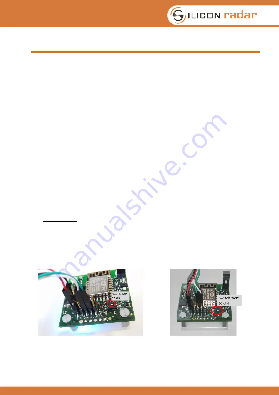
To update or change the microcontroller firmware, the board has to be set in bootloader mode, as
shown in Figure 35. This is done by switching the DIP switch called MP to the ON position. Then
connect the module to the PC via a USB to UART cable using the external header. Please read
Section 2.1.1 about the external header connection. Connect cable TX to MR (microcontroller RX)
and cable RX to MT (microcontroller TX).
Make sure to use a cable with 3.3V TTL levels!
Find and install the flash tool stm32flash in the Firmware folder of the provided Install Package.
Copy the desired firmware from the ‘Firmware\SiRad_Simple’ folder of the Install Package into the
stm32flash folder. Edit the batch file stm32flash.bat and replace the COM port with the COM port of
your USB to UART cable and the firmware name with the desired firmware, marked here:
stm32flash.exe -b 115200 -w
SiRad_Simple_<version>.bin
-v -g 0x0
COMx
Run the batch file and the microcontroller gets programmed. After about 30 seconds the
programming is finished. Switch the DIP switch MP back to the OFF position and do a power cycle
to reset the module.
You can find the firmware ‘SiRad_Simple_L8_TRX_120_<version>.bin’ in the provided Install
Package in the folder ‘Firmware\SiRad_Simple’.
5.2 WiFi Module
Connect the sensor using a USB to UART cable like shown in Figure 36 using the external header.
Please read Section 2.1.1 about the external header connection. Switch the DIP switch called WP
to the ON position. Then connect cable TX to WR (WiFi RX) and cable RX to WT (WiFi TX).
Make
sure to use a cable with 3.3V TTL levels!
Now connect the power Jumper J2 to enable the supply
voltage for the WiFi module.
Figure 35: Firmware update configuration
Figure 36: WiFi module update configuration