


AN685
Rev. 0.4
15
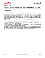
Figure 15. Differential BIFA used in 4455-LED-434 (4455CLED-434) Development Boards
The BIFA antenna in Figure 15 with the printed balun transformer has a single-ended 50
input, thus between the
antenna and the RF IC a 50
matching network is also required. The printed balun drives a differential BIFA and
the impedance match is done by a differential strip line. Furthermore, it is necessary to keep at least 2 mm space
between the entire antenna and the border of the PCB to ensure a reliable antenna input impedance and radiating
characteristic.
Silicon Labs has tested the use of this type of BIFA antenna to ensure its performance. For example, the input
impedance of the BIFA antenna at 868 MHz is shown in Figure 16.