


ToolStick-F321DC
12
Rev. 0.1
6.8. Using ToolStick Terminal
This section describes how to use ToolStick Terminal to communicate with UART from the PC to the daughter card
through the ToolStick Base Adapter.
1. If the Silicon Laboratories IDE is open, close the IDE. The IDE and the ToolStick Terminal cannot communicate
with the daughter card simultaneously.
2. Open ToolStick Terminal from the
Start
→
Programs
→
Silicon Laboratories
menu.
3. Go to the
ToolStick
→
Settings
menu.
4. Under “Pin Settings”, change GPIO0 / RTS to “
GPIO Output - Push Pull
” and click “OK.” The rest of the default
settings are correct for the C8051F321 Features Demo.
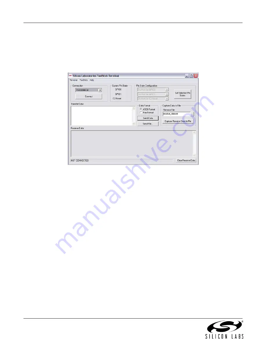
5. In the top, left-hand corner of the Terminal application, available devices are shown in the drop-down
Connection menu. Click “
Connect
” to connect to the device. In the “
Receive Data
” window, text indicating the
blink rate of the LED will appear.
6. Turn the potentiometer on the daughter card and see that the blink rate is updated on the daughter card and the
new blink rate is printed to the Terminal.
In addition to the standard two UART pins (TX and RX), there are two GPIO/UART handshaking pins on the
ToolStick Base Adapter that are connected to two port pins on the target microcontroller. ToolStick Terminal is used
to configure and read/write these pins. For the
F321DC_FeaturesDemo
, one of these GPIO pins is connected to
an external interrupt pin on the C8051F321. The following steps describe how to change the level of one of the
GPIO pins and trigger an interrupt on the target microcontroller. The interrupt forces the firmware to switch modes
and send a pulse-width modulated (PWM) signal to the LED instead of blinking the LED using an on-chip Timer.
1. In ToolStick Terminal, under Pin State Configuration, select “
Set GPIO0 Logic Low
” and click on “
Set Selected
Pin States
.” This changes the level of the GPIO0 pin from
Logic High
to
Logic Low
and triggers a level-
sensitive interrupt on the microcontroller.
2. In the Receive window, see that the printed text has changed to indicate the LED PWM duty cycle.
3. Turn the potentiometer on the daughter card to change the brightness of the LED on the daughter card.
4. Change the GPIO0 pin state back to
Logic High
and notice that the firmware switches back to blinking the
LED.
The firmware on the C8051F321 target microcontroller does not need to be customized to use the UART and
communicate with ToolStick Terminal. The firmware on the microcontroller should write to the UART as it would in
any standard application and all of the translation is handled by the ToolStick Base Adapter.


