


C 8 0 5 1 T 6 2 0 / 2 - D K
4
Rev. 0.4
5. Software Overview
The following software is necessary to build a project, download code to, and communicate with the target
microcontroller.
8051 Evaluation Toolset
Silicon Labs Integrated Development Environment (IDE)
Other useful software that is provided on the development kit CD and the Silicon Labs Downloads website
(
www.silabs.com/mcudownloads
) includes:
Configuration Wizard 2
Keil µVision2, µVision3, and µVision4 Drivers
MCU Production Programmer and Flash Programming Utilities
5.1. 8051 Evaluation Toolset
The Silicon Labs IDE has native support for many third-party 8051 toolsets. Included with this kit is an 8051
evaluation assembler, compiler, and linker. For further information on the tools, including limitations, see the
corresponding application note. Application notes can be found in the documentation section of the Development
Kit CD or on the Silicon Labs web site (
http://www.silabs.com/appnotes
). See Table 1 for a list of supported toolsets
and associated application notes.
5.2. Silicon Labs IDE
The Silicon Labs IDE integrates a source-code editor, source-level debugger, and in-system programmer. The
following sections discuss how to open an example project in the IDE, build the source code, and download it to the
target device.
5.2.1. Running the T620_Blinky or T622_Blinky example program
The T620_Blinky or T622_Blinky example program blinks an LED on the target board.
1.
Open the Silicon Labs IDE from the Start menu.
2.
Select
Project
Open Project
to open an existing project.
3.
Browse to the
C:\SiLabs\MCU\Examples\C8051T620_1_T320_3\Blinky or SiLabs\MCU\Exam-
ples\C8051T622_3_T326_7\Blinky
directory (default) and select the T620_Blinky_C.wsp pr
T622_Blinky_C.wsp project file. Click
Open
.
4.
Once the project is open, build the project by clicking on the
Build/Make Project
button in the toolbar or
selecting
Project
Build/Make Project
from the menu.
Note: After the project has been built the first time, the
Build/Make Project
command will only build the
files that have been changed since the previous build. To rebuild all files and project dependencies, click
on the
Rebuild All
button in the toolbar or select
Project
Rebuild All
from the menu.
5.
Before connecting to the target device, several connection options may need to be set. Open the
Connec-
tion Options
window by selecting
Options
Connection Options...
in the IDE menu. First, select the
“USB Debug Adapter” option. Next, the correct “Debug Interface” must be selected. C8051T62x/32x
devices use Silicon Labs “C2” 2-wire debug interface. Once all the selections are made, click the
OK
but-
ton to close the window.
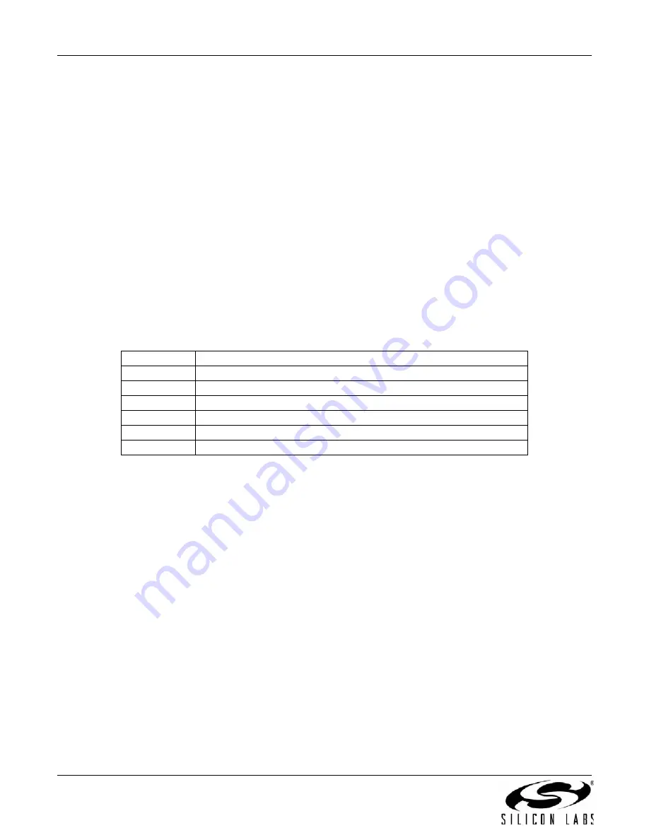
Table 1. Supported Third Party 8051 Toolsets
Toolset
Application Note
Keil
“AN104: Integrating Keil 8051 Tools into the Silicon Labs IDE”
Raisonance
“AN125: Integrating Raisonance 8051 Tools into the Silicon Labs IDE”
Tasking
“AN126: Integrating Tasking 8051 Tools into the Silicon Labs IDE”
HI-TECH
“AN140: Integrating Hi-TECH 8051 Tools into the Silicon Labs IDE”
SDCC
“AN198: Integrating SDCC 8051 Tools into the Silicon Labs IDE”
IAR
“AN236: Integrating IAR 8051 Tools into the Silicon Labs IDE”
Содержание C8051T620-DK
Страница 18: ...C8051T620 2 DK 18 Rev 0 4 8 Schematics Figure 14 C8051T62x Motherboard Schematic 1 of 2 ...
Страница 19: ...C8051T620 2 DK Rev 0 4 19 Figure 15 C8051T62x Motherboard Schematic 2 of 2 ...
Страница 20: ...C8051T620 2 DK 20 Rev 0 4 Figure 16 C8051T62x Emulation Daughter Board Schematic ...
Страница 21: ...C8051T620 2 DK Rev 0 4 21 Figure 17 C8051T620 QFN 32 Daughter Board Schematic ...
Страница 22: ...C8051T620 2 DK 22 Rev 0 4 Figure 18 C8051T622 QFN 24 Daughter Board Schematic ...
Страница 23: ...C8051T620 2 DK Rev 0 4 23 Figure 19 C8051T320 QFP 32 Daughter Board Schematic ...
Страница 24: ...C8051T620 2 DK 24 Rev 0 4 Figure 20 C8051T321 QFN 28 Daughter Board Schematic ...
Страница 25: ...C8051T620 2 DK Rev 0 4 25 Figure 21 C8051T326 QFN 28 Daughter Board Schematic ...
Страница 26: ...C8051T620 2 DK 26 Rev 0 4 Figure 22 C8051T327 QFN 28 Daughter Board Schematic ...


