


6
LE200+MB200
Datum 09.11.2009
Art.Nr. 84882
Änd. Stand 326/09
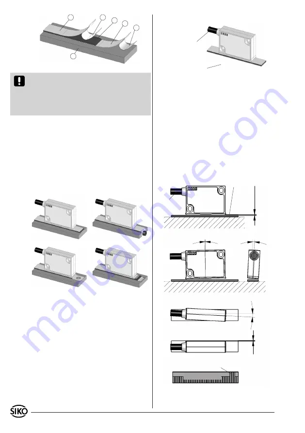
Fig. 2
Fig. 3
Fig. 4
Fig. 5
Fig. 1: Mounting of the magnetic strip
2
1
3
4
5
6
Fig. 6: Definition of counting direction / mounting
Travel direction sensor,
sine before cosine
Direction of
outgoing cable
Gap sensor/magnetic strip
Maximum alignment error
< 1°
< 3°
(<1°*)
active
side
Direction of
outgoing cable
±0.5
< 3°
(<1°*)
* with fixed refe-
rence signal "RB"
Position of the reference point relating
to the marking on the magnetic strip
0,1mm ... 0,8mm
with
out r
efer
en
ce poin
t
0,1mm ... 0,5mm
with r
efer
en
ce poin
t
0
0
2
NNNN 0200
Attention!
Do not expose the system to magne-
tic fields. Any direct contact of the magnetic strip
with magnetic fields (e.g. adhesive magnets or
other permanent magnets) is to be avoided. Sen-
sor movements during power loss are not captured
by the follower electronics.
Mounting examples
Mounting with chamfered ends (fig. 2) is not re-
commended unless the strip is installed in a safe
and protected place without environmental influ-
ences. In less protected mounting places the strip
may peel. There we recommend mounting accord.
to fig. 3 and 4.
Mounting in a groove (fig. 5) best protects the
magnetic strip. The groove should be deep enough
to totally embed the magnetic strip.
When mounting the magnetic sensor, ensure that
the gap between strip & sensor and the max.
admissable deviation are maintained over the
total measuring length (see fig. 7)!
The max. gap between sensor head and magnetic
band without cover strip is 0,8mm (with reference
point max. 0,5mm). When using cover strip, the
gap is reduced by the thickness of cover strip
including its adhesive tape. Sensor must not
touch the magnetic strip.
•
3.3. Mounting the sensor
Use two screws to fix the magnetic
sensor LE200
via the elongated holes. We recommend to use the
enclosed fixing screws and washer springs (faste-
ning torque 1Nm).
Cable layout should avoid damages due to cable
strain or other machine parts. If necessary use
a drag chain or protective hose and provide for
strain relief.
Sensor must be aligned correctly with respect
to the counting direction
(see fig. 6). This can
be ignored if counting direction can be changed
via the follower electronics.
Place distance gauge with its complete surface
between sensor and magnetic tape.
Note:
only
•
•
•
relevant for sensors without reference signal R.


