

Quick Start Guide
AP04 · Date
22.04.2015 · Art.
No.
88398 · Mod.
status
146/15
SIKO GmbH
Weihermattenweg 2
79256 Buchenbach
www.siko-global.com
Phone
: + 49 7661 394-0
Fax
: + 49 7661 394-388
Service
AP04
Absolute / Electronic
Position Indicator
For detailed documentation please refer under
http://www.siko-global.com/p/ap04
General information
Prior to installation, including in hazard areas, read the Installation Instruc-
tions (download from the internet). It contains the safety instructions, hints
and technical data to be observed during installation. Subject to change with-
out notice.
Caution
In order to ensure reliable functioning of this product, take care to transport,
store, position and mount it appropriately. Exercise care when you operate and
maintain the device. Only properly qualified personnel is authorized to install
and operate this product.
Safety information
It is important for safety reasons that you read and understand the below
instructions before you install the system:
•
Installation, connection, commissioning and maintenance shall be done by
properly qualified personnel.
•
It is the responsibility of the customer to ensure that the personnel con-
cerned read and follow the instructions and directions of this Guide and of
the Installation Instructions.
•
It is the responsibility of the customer to ensure that the position indicator
is correctly connected and configured.
•
Only personnel specifically trained by SIKO shall execute repair and mainte-
nance work.
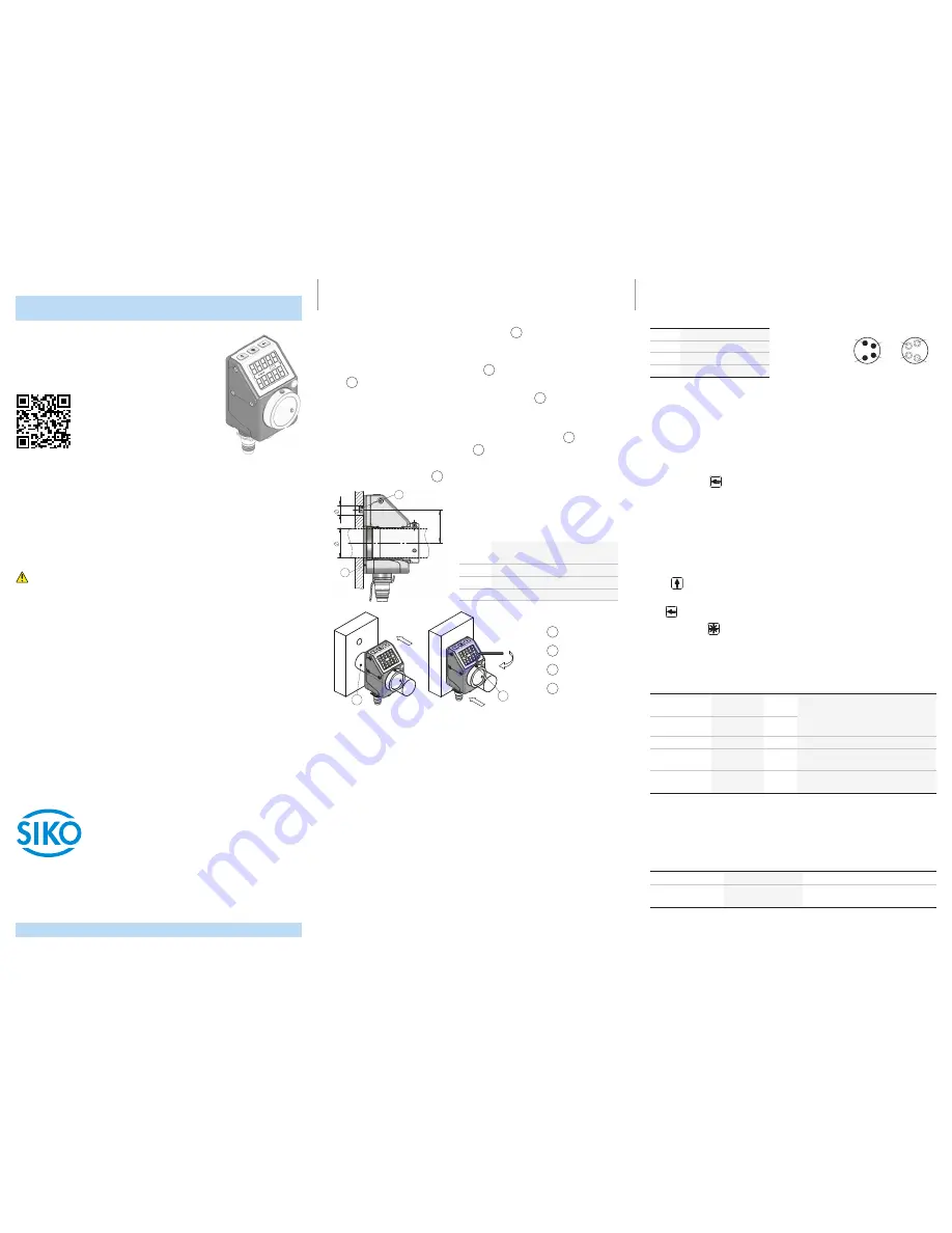
Mechanical mounting
Preparing mounting:
•
Stick the attached self-adhesive sealing plate
1
(foam rubber) onto the
bearing support or intermediate plate (to ensure the type of protection,
correct uneven spots).
•
Make the bore (ød) for torque support
2
at distance (L1) to the drive shaft
3
.
•
Pay attention to the diameter (øD) of the drive shaft
3
.
Mounting:
•
Push the position indicator incl. sealing plate onto the shaft
3
until reach-
ing the stop. Insert torque support
2
into the existing bore (non-dis-
torted mounting). A long hole for the torque support is recommended.
•
Tighten grub screws M3
4
with max. 0.2 Nm.
dim. ød ø6 (type A)
ø10
+0.8
(type B)
dim. L1 22
dim. øD ø20 (clearance fit)
dim. øD ø14 (clearance fit / Protection IP65rd)
1
Sealing plate
2
Torque support
3
Shaft
4
Grub screw
Electrical Installation
The location should be selected to ensure that no capacitive or inductive inter-
ferences can affect the position indicator or the connection lines!
•
All lines for connecting the position indicator must be shielded. Strand
cross sections of lines ≥0.14 ... ≤0.5 mm².
•
Do not disconnect or close live connections.
•
Perform wiring work in the de-energized state only.
•
Use strands with suitable ferrules.
•
Prior to switching on check all mains and plug connections.
•
The running of wiring parallel to the mains supply should be avoided. Use
screening shields or metallized housings.
•
Contactor coils must be linked with spark suppression.
Pin assignment
PIN
Designation
1
DÜB/CANL
2
DÜA/CANH
3
+UB
4
GND
Commissioning
The position indicator has a two-line display with special characters and three
control keys. The keys serve for position indicator parameterization and con-
trol. In the basic state (factory setting), the 1st line displays the actual value
and the 2nd line the set point.
After applying supply voltage, the position indicator will be on the uppermost
level of the menu structure (default/delivery state).
•
Pressing the
key starts the parameter / programming mode (see User
manual).
Configuration
(only CAN + RS485/SIKONETZ3,4; RS485/SIKONETZ5 see User manual)
The required parameters are set in the configuration mode. On the 1st line of
the display, the parameter will be shown and on the 2nd line the respective
value will be displayed.
Press
key for changing actual value and / or the blinking digit when enter-
ing a multi-digit value.
The
key serves for switching to the next digit in case of multi-digit numbers.
By pressing the
key, the set value is acknowledged and saved non-vola-
tilely. If no key is pressed, the configuration mode will be exited after ~30 s
without saving the latest value displayed, i. e. the original value will be main-
tained.
Parameter
Value range
Default Default Meaning/Remark
RS485 SIKO-
NETZ: Id
0 ... 31
1
bus address
NOTICE
Restart is required after changing these
parameters!
CAN: Id
1 ... 127
1
RS485: SnEt
3, 4
4
SIKONETZ communication protocol
RS485 SIKO-
NETZ5: bAUd
19.2, 57.6,
115.2kbd
57.6
SIKONETZ baud rate (e. g. 57.6 kbit/s)
CAN: bAUd
125, 250,
500, 1000kbd
250
CAN baud rate (e. g. 250 kbit/s)
Additional configuration parameters can be found in the detailed documenta-
tion.
Technical data
Electrical data
Additional information
Operating voltage
24 V DC ±20 %
Current consumption ~20 mA
if operated with LEDs, additional ~3 mA
per LED
viewing side = plug-in side
Bus OUT
Bus IN