SIIG AV-GM06Y3-S1 Скачать руководство пользователя страница 9


7


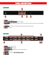
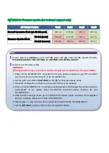
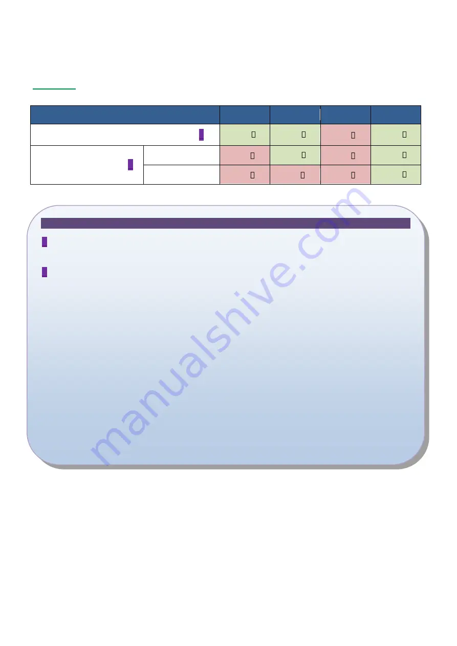
SW MAIN for firmware update (for technical support only) 
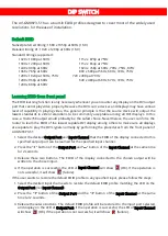
 

DIP Switch Position


Pin#1 

Pin#2 

Pin#3 

Pin#4 

Normal Operation Mode [via RS-232 port] 

1


OFF [ ] 

OFF [ ] 

ON [ ] 

OFF [ ] 

Firmware Update Mode 

2


Block A [main] 

ON [ ] 

OFF [ ] 

ON [ ] 

OFF [ ] 

Block B [remote] 

ON [ ] 

ON [ ] 

ON [ ] 

OFF [ ] 


Note 

1

  Factory default for 

SW Main

 is pin#1-OFF 

[

]

, pin#2-OFF 

[

]

, pin#3- ON 

[

]

, & pin#4-OFF 

[

]

PLEASE MAINTAIN THIS SETTING AT ANYTIME FOR REGULAR USE!


2

  Sequence for firmware update 

WARNING! 
[Firmware update only can be done via RS-232 port and connection to PC set at COM1) 

1. Power off the AV-GM06Y3-S1. Execute the firmware update program on your PC via COM1 

port connection to the RS-232 port of the AV-GM06Y3-S1. 

2. Set the pin#1 and pin#3 of 

[SW Main]

 at ON 

[

]

 for firmware update mode. 

3. Set pin#2 at respective positions to assign which Block to be updated. 

4. Power on the AV-GM06Y3-S1. The firmware update program should begin this update sequence 

automatically.  If  not,  please  check  the  RS-232  connection  status  between  PC  and 
AV-GM06Y3-S1. 

5.  After  the  OK  message  shows  up  to  indicate  the  firmware  update  sequence  for  designated 

Block is complete, please turn off the AV-GM06Y3-S1. 

6. Repeat step 3 ~ step 6 if you want to update the firmware of the remaining Blocks. 

7. Set the 

[SW Main]

 switch position to Normal Operation Mode. 

8. Power on the AV-GM06Y3-S1. 

Содержание AV-GM06Y3-S1

Страница 1: ...8x8 DVI Matrix User Manual P N AV GM06Y3 S1...

Страница 2: ...attempt to service this unit yourself except where explained in this manual Provide proper ventilation and air circulation and do not use near water Keep objects that might damage the device and assu...

Страница 3: ...FEATURES DVI 1 0 compatible single link Allows any source to be displayed on multiple displays at the same time Allows any DVI display to view any DVI source at any time Supports default EDID and lear...

Страница 4: ...S 232 Ethernet IR remote control Electro optical characteristics 25 Carrier frequency 36 40kHz DVI connector Type DVI I 29 pin female RS 232 connector DE 9 9 pin D sub female DIP switch SW Main 4 pin...

Страница 5: ...3 USB or RS 232 control must be connected either one at a time Connecting both types of cables may cause command confusion...

Страница 6: ...o select the number of input source and display channel 4 IR SENSOR IR sensor for receiving the IR commands from the IR remote 5 Ext IR IR receiver Rear Panel 6 RS 232 RS 232 control port 7 DVI D INPU...

Страница 7: ...HARDWARE INSTALLATION AV GM06Y3 S1 1 Connect all sources to DVI Inputs on the 8x8 DVI Matrix 2 Connect all outputs to DVI devices 3 Connect the power cord to the 8x8 DVI Matrix 4 Power on the 8x8 DVI...

Страница 8: ...to learn the EDID of the lowest capable DVI display among others to make sure all displays are capable to play the DVI signals normally by performing the procedures from the front panel of AV GM06Y3...

Страница 9: ...firmware update program on your PC via COM1 port connection to the RS 232 port of the AV GM06Y3 S1 2 Set the pin 1 and pin 3 of SW Main at ON for firmware update mode 3 Set pin 2 at respective positi...

Страница 10: ...emote Control Firstly please push one of the INPUT buttons to choose which HDMI input source you are going to setup After that you can have multiple outputs playing the same content from the selected...

Страница 11: ...ng the control software located on the included software CD it is possible to fully control the matrix switch by either RS 232 or Ethernet connection There are three primary sections of the control so...

Страница 12: ...t control Note After making changes to the Ethernet settings the user must power cycle the unit for the new settings to become effective If the unit receives commands from both Ethernet and RS 232 por...

Страница 13: ...Area on the left side to send that Input to all Outputs Choose the Unselect All Output menu item to de select all currently selected Outputs from the currently selected Input Choose one of the Select...

Страница 14: ...and select the Input to route to it The connection line will move to indicate the new route To route an Input to more than one Output select the Outputs you wish to affect in the Output Selection Are...

Страница 15: ...F5 Output F selects Input 5 B6 Output B selects Input 6 F6 Output F selects Input 6 B7 Output B selects Input 7 F7 Output F selects Input 7 B8 Output B selects Input 8 F8 Output F selects Input 8 C1...

Страница 16: ...14 D7 Output D selects Input 7 H7 Output H selects Input 7 D8 Output D selects Input 8 H8 Output H selects Input 8...

Страница 17: ...t Under no circumstances will a unit be accepted without a return authorization number The warranty is in lieu of all other warranties expressed or implied including without limitations any other impl...

Отзывы: