background image

‡ SIGNET

 2540 High Performance Flow Sensor

Page 4 of 8

lower hex nut 

and jam nuts

sensor flange

18 inch 

threaded rods

359 mm (14.14 in)

process pipe (side view)

direction of flow

alignment rod

Upper hex nuts

(3/16 x 1/4-20)
1/4 in. lock 

washers


sensor

fitting

bleed valve

cable 

grommit

25mm

(1.0 in.)

protector plate 

hex nut (3/16 x 

1/4-20)

protector plate 

removed during 

sensor installation 

protector plate 

cap nuts

lower hex nuts

(3/16 x 1/4-20)

jam nuts

(5/32 x 1/4-20)

359 mm

(14.14 in.)

sensor

fitting

UNDER PRESSURE!

alignment
rod

sensor
flange

process pipe

(top view)

The flow alignment rod 

MUST

 be

parallel to the process pipe as shown.

flow direction

F.

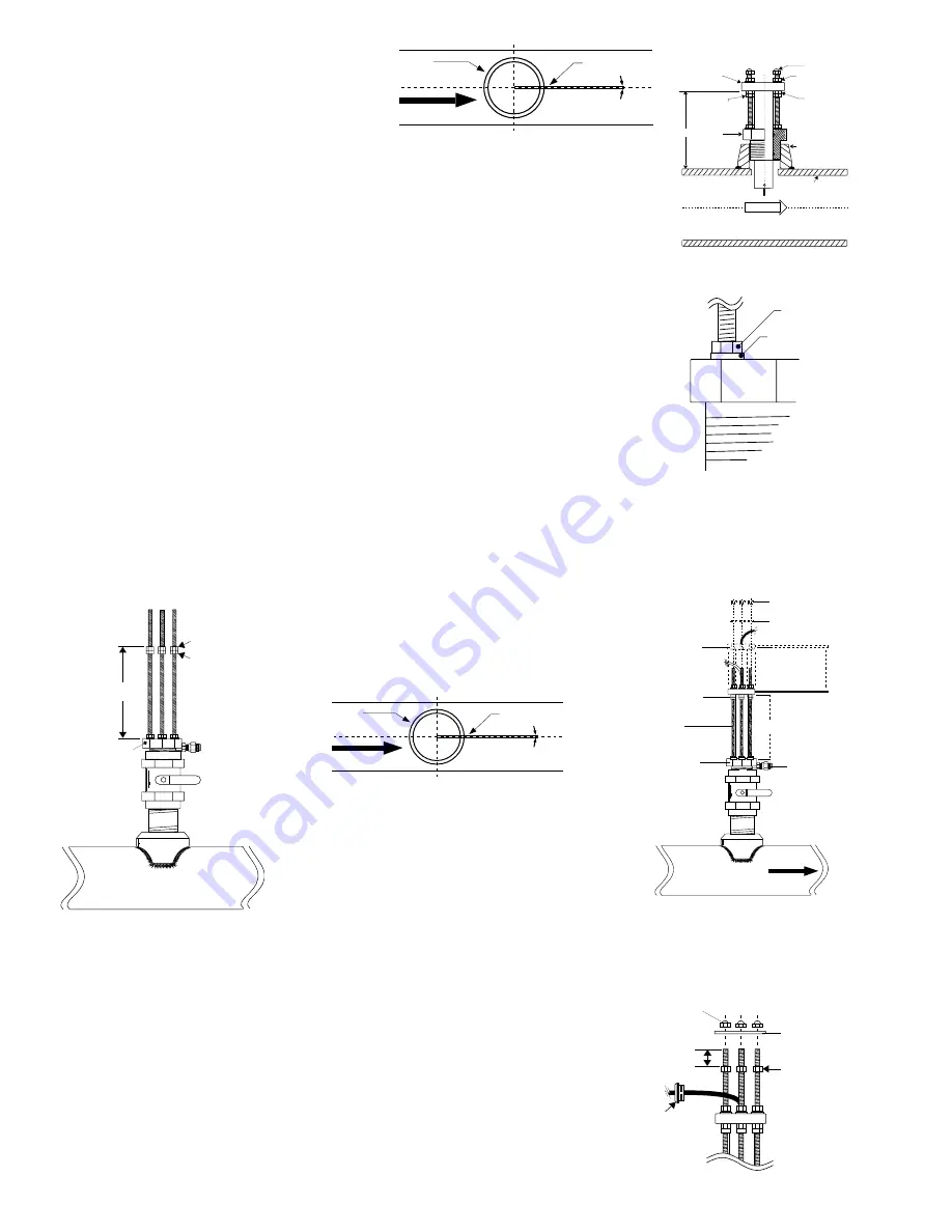
  Thread protector plate hex nuts onto each of the three threaded rods.  Adjust each hex nut to a

height of approximately 25 mm (1 in.) from the top of each rod.  Remove the black plastic cable
grommet in top of sensor with a screwdriver.  Slide the grommet up the cable away from sensor.
(Fig. 12)

Fig. 9

Fig. 10

Fig. 11

D.

Place the alignment rod in the alignment hole on the

sensor flange.  Align the flange so rod is parallel to the
process pipe.  (Fig. 6)

E

.  

Thread upper hex nuts with lock washers until they

contact the sensor flange and tighten.  Check for proper "H"
dimension and readjust if necessary. (Fig. 7)

4.7  Hot-Tap Sensor Installation

A.

Thread one hex nut onto each of the three threaded

rods included in package.  Install threaded rod with a lock
washer onto the sensor fitting.  Secure rods in place by tightening each hex nut against the sensor fitting.
(Fig. 8)

B.

Thread one jam nut and lower hex nut onto each threaded rod so that the top surface of each

nut is 359 mm (14.14 in.) from the top surface of the sensor fitting.  Secure each hex nut with a
jam nut. (Fig. 9)

CAUTION:  This setting is critical to ensure an adequate sensor seal and to prevent the rotor
from hitting the isolation valve orifice during installation.

C.  

Wipe the sensor body with a dry, clean cloth.  Orient the alignment hole on the sensor flange

to point 

downstream

.  Place the slotted flange over the threaded rods.  Lower the sensor into the

fitting until the sensor flange rests on the lower hex and jam nuts.

D.

  Secure the sensor with lock washers and upper hex nuts on the top of the flange.  Before

tightening, align the sensor flange so that the alignment rod is parallel and level with the process
pipe. (Fig. 10 & Fig. 11)

E.

  Make sure the bleed valve is closed (full clockwise position).

"

H

"

process
pipe wall I.D.

sensor
fitting

upper hex nuts
& lockwashers

lower hex nuts

jam nuts

sensor
flange

cap nuts

female pipe fitting

FLOW

sensor fitting

hex nut

Lock washer

alignment
rod

sensor
flange

process pipe

(top view)

The flow sensor alignment rod 

MUST 

be

parallel to the process pipe as shown.

flow direction

Fig. 6

Fig. 7

Fig. 8

Fig. 12

Содержание 2540

Страница 1: ...D 5x I D 90 Elbow 50x I D 5x I D 40x I D 5x I D 25x I D 5x I D 2 x90 Elbow 2 x 90 Elbow 3 dimensions Valve Gate 2 Sensor Mounting Position Vertical mounting is recommended for best overall performance Mount at a maximum of 45 when air bubbles are present DO NOT mount on the bottom of the pipe when sediments are present 45 0 Process Pipe 45 1 Location of Fitting Recommended sensor upstream downstre...

Страница 2: ...fitting from sensor assembly E Thread sensor fitting into pipe fitting Fig 1 4 4 Hot Tap Fitting Installation A Install the pipe fitting on the outside diameter of the pipe according to the manufacturer s instructions Failure to follow these instructions may result in serious bodily injury and or product failure B Install the pipe nipple and isolation valve ball or gate valve onto the external pip...

Страница 3: ... X I D Example 10 inch schedule 40 wrought steel Wall thickness 0 365 in Inside diameter 10 02 in H 15 39 0 365 0 10 X 10 02 H 356 18 mm 14 023 in Record your sensor s H dimension for future reference H ___________ After correct dimensions are calculated and recorded the sensor can be installed in the fitting The Standard and Hot Tap versions require substantially different procedures 4 6 Standard...

Страница 4: ...allation A Thread one hex nut onto each of the three threaded rods included in package Install threaded rod with a lock washer onto the sensor fitting Secure rods in place by tightening each hex nut against the sensor fitting Fig 8 B Thread one jam nut and lower hex nut onto each threaded rod so that the top surface of each nut is 359 mm 14 14 in from the top surface of the sensor fitting Secure e...

Страница 5: ...tool shaft clockwise until the sensor flange contacts the lower hex and jam nuts Thread the upper hex nuts down until they contact the sensor flange Tighten the upper hex nuts to secure the sensor Fig 14 J Remove cap nuts and withdraw the installation tool Be careful to not damage cable Snap cable grommet into top of sensor and replace protector plate and cap nuts Fig 15 swivel mount w cable port ...

Страница 6: ...ring for sensor fitting 198 801 186 1224 0021 Optional EPR O ring for sensor fitting 198 820 006 P52504 3 Replacement rotor pin tungsten carbide 159 000 866 P52504 4 Replacement rotor pin 316 ss 159 000 867 3 2540 090 1 Instruction manual 159 000 284 1 O ring required for standard sensor 2 for Hot Tap Wrought Steel Pipe Per ANSI 36 10 Stainless Steel Pipe Per ANSI B36 19 Wrought Steel Pipe Per ANS...

Страница 7: ... 20 in 0 9146 0 242 65 602 248 305 22 in 0 7334 0 194 81 811 309 654 22 in 0 7506 0 198 79 936 302 558 24 in 0 6175 0 163 97 166 367 773 24 in 0 6311 0 167 95 072 359 848 SCH 40S STAINLESS STEEL PIPE PER ANSI B36 19 SCH 40 WROUGHT STEEL PIPE PER ANSI B36 10 K Factor K Factor A Factor A Factor K Factor K Factor A Factor A Factor PIPE PULSES PULSES U S PIPE PULSES PULSES U S SIZE U S GAL LITER GPM H...

Страница 8: ...s depend on the lowest maximum rating of the components associated with the system In other words the Hot Tap system is only as strong as its weakest link For example a ball valve a component of the system is rated at a maximum 100 psi 175 F limiting the entire system s maximum pressure temperature rating to 100 psi 175 F All higher maximum specifications MUST yield to the component with the lowes...

Отзывы: