-
2 -
DC:
1. Insert the positive and negative wires into the PWR1
(+,-) and PWR2 (+,-) on the 3-contact terminal block
connector.
2. Tighten the screws to prevent the wires from loosening.
3. Verify that the external DC power requirements for the
switch can be met as listed below:
24-72VDC
5.
Verify Switch Operation
Verify basic switch operation by checking the system LEDs.
When operating normally, the System, AC Power and/or
DC Power LEDs should be on and green depending on the
number and type of power sources used.
6.
Connect to the Web User Interface
1. Connect a PC to the switch through one of the RJ-45
ports.
2. The switch has a default management IP address of
192.168.1.1 and a subnet mask of 255.255.255.0. You
must set your PC IP address to be on the same subnet
as the switch (that is, the PC and switch addresses
must both start with 192.168.1.x).
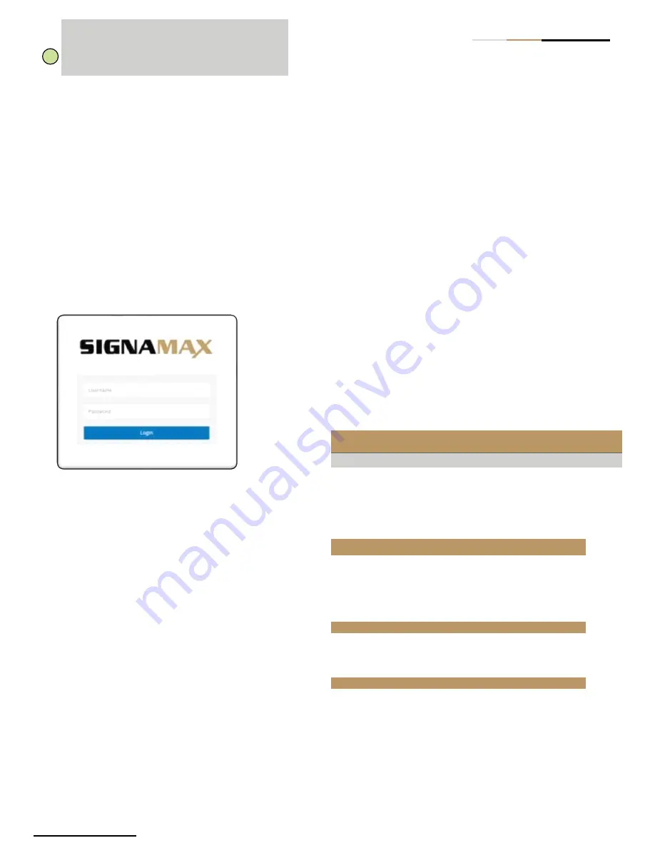
3. Log in to the web interface or CLI using the default
settings:
username “admin” and password “admin”.
7.
Connect
Network Cables
1. For RJ-45 ports, connect 100-ohm Category 5, 5e or
better twisted-pair cable.
2. For the SFP/SFP+ slots, first install SFP/SFP+
transceivers and then connect fiber optic cabling to the
transceiver ports. All Signamax 100Mb and 1Gb SFPs
are supported on the SFP Ports. All Signamax 1G and
10G SFPs are supported on the SFP+ Ports.
Quick Start Guide
3. As connections are made, check the port status LEDs
to be sure the links are valid. Press the Mode/Reset
button less than 2 seconds to change from Ethernet to
PoE status. RJ45 Ports:
•
On/Blinking Green
— Port has a valid 1Gb link.
•
On/Blinking Amber
— Port has a valid 10/100Mb
link.
SFP Ports:
•
On/Blinking Amber
— Port has a valid 100Mb link.
•
On/Blinking Green
— Port has a valid 1Gb link.
SFP+ Ports:
•
On/Blinking Blue
— Port has a valid 10Gb link.
•
On/Blinking Green
— Port has a valid 1Gb link.
Blinking indicates network activity.
8.
Connect to the Console Port
1. Connect a PC to the switch console port using the
included console cable.
2.
Configure the PC’s serial port: 115200 bps, 8
characters, no parity, one stop bit, 8 data bits, and no
flow control.
3. Log in to the CLI using the default settings: username
“admin” and password “admin”.
9.
Mode/Reset Button
Hardware Specifications
Press
Time
Switch Action
System LED
Port
LEDs
2-7
Reboot the switch
Blinking Green
Off
> 7
Reset the switch to
factory default and reboot
Blinking Green
On
Switch Chassis
Size
(W x H x D)
17.4 x x8.1 x 1.73in (44.2 x 21.1 x
4.4cm)
Weight
1 Power Supply: 6.8lb (3.1kg)
Temperature
Operating: 32 to 104°F (0 to 40°C)
Storage: -4 to 158°F (-20 to 70°C)
Humidity
10 to 95% (non-condensing)
Power Specification
AC Input
Power
100 - 240 V AC, 50/60 Hz
DC Input
Power
24 - 72 V DC
Regulatory Compliances
Emissions
CE Mark
•
EN 55022, Class A
FCC Part 15 Subpart B Class A
Immunity
IEC 61000-3-3,IEC61000-4-2/3/4/5/6/8
Note:
For International use, you may need
to change the AC line cord. You must use a
line cord set that has been approved for the
socket type in your country.
i


