background image

065-1096 10/100/1000BaseT/TX TO 1000BaseSX/LX GIGABIT SFP MEDIA CONVERTER


4 Installation 

In this chapter, we will take a look at how to install the Converter within its operating 
environment. To install your Media Converter, please see the following procedures: 
 

 Location 

 10/100/1000BaseT/TX port 

  Gigabit SFP slot 

  Link Fault Signaling 

 Desktop 

installation 

  Powering on unit 

4.1 Location 

The location selected for installing the Converter may greatly affect its performance. 
When selecting a site, we recommend considering the following rules: 
 
1.  Install the Converter in a fairly cool and dry place.  See 

Technical Specifications 

for 

the acceptable temperature and humidity operating environments. 

2.  Install the Converter in a location free from strong electromagnetic field generators 

(such as motors), vibration, dust, and direct exposure to sunlight. 

3.  Leave at least 10cm of space at the front and rear of the unit for ventilation. 

4.  Affix the provided rubber pads to the bottom of the Converter for grip, and to 

protect the case from scratching. 

4.2 10/100/1000BaseT

/TX

 Port (RJ-45) 

The auto MDI/MDI-X and auto-negotiation on the RJ-45 port alleviates the worry of 
cabling configuration when connecting the Converter with a 10/100/1000Base-T device. 
It accepts both ‘straight-through’ and ‘cross-over’ Ethernet cables without the need to 
re-configure the port. Whether connecting to a switch, LAN card, or other network 
device via the RJ-45 port, simply plug and go!


4.3 

Gigabit SFP Slot 

To connect a fiber cable’s connector to the Converter’s SFP slot, slide the selected 
SFP module (mini-GBIC) into the SFP slot, making sure that the module’s receptors 
line up with the receptors at the back of the slot. Push until you hear a click. Once the 
module is inserted correctly, take the cable connector and turn it so that it will fit into 
the mouth of the module. Then push the connector into the mouth until its catches click 
into the receiving grooves in the module’s mouth. Use the appropriate type of multi-
mode or single-mode fiber, depending on the SFP module being used. The fiber optics 
transmit data at up to 1000 Mbps and can maintain data integrity over cable distances 
as long as 60 km or more, depending on the selected SFP (mini-GBIC) module. 


Warning: 

Because invisible laser radiation may be emitted from the aperture 
of the fiber port when no cable is connected, avoid exposure to 
laser radiation and do not stare into the open apertures.


Содержание 065-1096

Страница 1: ...10 100 1000BaseT TX to 1000BaseSX LX User s Manual Issue date April 2008 ...

Страница 2: ...ovide reasonable protection against harmful interference in a commercial installation This equipment generates uses and can radiate radio frequency energy and if not installed and used in accordance with the instructions may cause harmful interference to radio communication Operation of this equipment in a residential area is likely to cause harmful interference in which case the user will be requ...

Страница 3: ...1 6 Package Contents 2 2 HARDWARE DESCRIPTION 3 2 1 Product Overview 3 2 2 Product Illustrations 4 2 3 DIP Switches 4 3 LED INDICATORS 5 4 INSTALLATION 6 4 1 Location 6 4 2 10 100 1000BaseT TX Port RJ 45 6 4 3 Gigabit SFP Slot 6 4 4 Link Fault Signaling 7 4 5 Desktop Installation 7 4 6 Powering On the Unit 7 5 APPENDIX APPLICATION DIAGRAMS 8 5 1 Application Diagram I 8 5 2 Application Diagram II 8...

Страница 4: ...r upper case refers to your 10 100 1000BaseT TX to 1000BaseSX LX SFP Media Converter and converter first letter lower case refers to other converters 1 4 Features Standards IEEE 10 100BaseT TX IEEE 802 3ab 1000BaseT IEEE 802 3z 1000BaseSX LX Interface One 10 100 1000 Mbps Ethernet port Auto MDI MDI X support on RJ 45 port One SFP slot for a Gigabit Ethernet fiber optic link Extends distances up to...

Страница 5: ...Illuminated when failure occurs on fiber or copper link Illuminated when receiving link pulses from compliant devices Flashing when data packets being transmitted or received via fiber port DIP Switches DIP 1 LFS Enable disable Link Fault Signaling LFS Power 12V DC 0 5A external power supply adapter Frequency 50Hz to 60Hz Environment Temperature Relative Humidity Storage Relative Humidity Operatin...

Страница 6: ...t through when establishing connection between RJ 45 ports It features both an RJ 45 jack and an SFP slot which allows it to easily integrate a 1000BaseT network with a 1000BaseSX LX fiber network If the LFS DIP switch is set to ON the Link Fault Signaling function is enabled If the copper link is down the fiber port will be disabled by the Converter If the fiber port loses signal the copper port ...

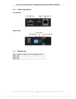
Страница 7: ... GIGABIT SFP MEDIA CONVERTER 2 2 Product Illustrations Front Panel Fiber SFP Slot LEDs Ethernet Port Rear Panel Power LED 2 3 DIP Switches DIP 1 Enables disables Link Fault Signaling LFS DIP 2 N A DIP 3 N A DIP 4 N A 4 DIP Switches Power Connector ...

Страница 8: ...ase see below for an interpretation of their functions LED Indicators 5 LED Condition Status On Green Unit is receiving power PWR Off Power off or failure On Green Fiber link up Flashing Green Data packets being transmitted or received via Fiber port LNK ACT Off Fiber link down On Green 1000 Base Mode 1000 Off 10 100 Base Mode On Green Copper link up Port LNK ACT Flashing Green Data packets being ...

Страница 9: ... on the RJ 45 port alleviates the worry of cabling configuration when connecting the Converter with a 10 100 1000Base T device It accepts both straight through and cross over Ethernet cables without the need to re configure the port Whether connecting to a switch LAN card or other network device via the RJ 45 port simply plug and go 4 3 Gigabit SFP Slot To connect a fiber cable s connector to the ...

Страница 10: ...ivity 4 5 Desktop Installation Follow the instructions listed below to install the Converter in a desktop location 1 Locate the Converter in a clean flat and safe position that has easy access to AC power 2 Affix the four 4 self adhesive rubber pads to the underside of the Converter 3 Apply AC power to the Converter The green PWR LED on the rear panel should light 4 Connect cables from the network...

Страница 11: ...rea network It is providing a 10 100 1000Mbps full duplex link to a variety of Fast Ethernet or Gigabit network devices within a LAN Switch CONVERTER CONVERTER Switch 5 2 Application Diagram II In the figure below the Converter is functioning as a server aggregation for an enterprise or LAN configuration It is providing a 10 100 1000Mbps full duplex link to a workgroup of 10 100 1000 switches loca...

Отзывы: