background image

EAN-Startup Guide-3000-OEM 


© SightLine Applications, Inc.


                                                          3 

5


Hardware Bench Setup 


IMPORTANT

: To prevent damage to the hardware boards, use a conductive wrist strap attached to 

a good earth ground. Before picking up an ESD sensitive electronic component, discharge built up 
static by touching a grounded bare metal surface or approved anti-static mat. 


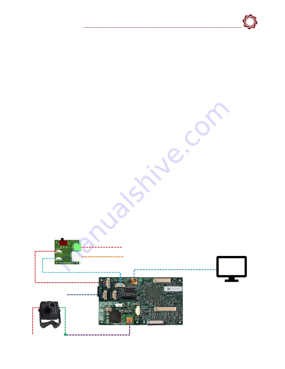
The 3000-HDSDI-IN is connected to J4 on the 3000-OEM or VIN1 on the SLA-3000-IO. 

The SLA-DIST 

provides power switch and standard bench interface connections for power and ethernet.


IMPORTANT:

  To prevent voltage spikes to the board, plug in the power adapter to an AC power 

source first and then connect to the board. 

Cable connections: 


SLA-CAB-MCX2BNC: Connects to J1 (MCX jack) on the 3000-HDSDI-IN board and to the green BNC 
connector of the 1080p camera. The yellow BNC connector is  for analog use only


SLA-CAB-SMA2BNC:  Analog monitor cable (optional). Connects to J8 on the SLA-3000-mIO (VOUT 
on the SLA-3000-IO). 


SLA-CAB-ETH0:  Connects to the Ethernet port and to the network switch or host PC. 


SLA-CAB-0404: Connects to J3 on the SLA-DIST and J4 on the SLA-3000-mIO. Provides Ethernet to 
the 3000-OEM. 


SLA-CAB-0405: Connects to J2 on the SLA-DIST and J9 on the SLA-3000-mIO. Provides power to the 
3000-OEM.  


SLA-PWR-A12V (110-250VAC input / 12VDC output): Connects to the red power connector on the 
1090p camera. 


SLA-PWR-B12V (110-250VAC input / 12VDC output): Connects to J4 on the SLA-DIST (SLA-3000-
mIO). 


SLA-PWR-C12V (110-250VAC input / 12VDC output): Connects to J5 on the SLA-3000-IO. 

Power and network connectivity LEDs:


A green light on the 3000-IO or 3000-mIO board indicates that all boards are powered on. An 
amber light on the 3000-OEM board verifies network connection. 


Figure 3: Typical Bench Hardware Setup - SLA-3000-mIO 

Serial (0)


Network Switch or 
PC Direct


SLA-DIST


SLA-PWR-B12V 


Optional 

Analog  

Monitor 

SLA-CAB-0405 (J9)


SLA-CAB-0404 (J4)


SLA-CAB-MCX2BNC (VIN1) to camera


3000-OEM +  
SLA-3000-mIO on J1 + 
SLA-3000-HDSDI-IN on J4 

1080p Camera


SLA-PWR-A12V


J2 

SLA-CAB-ETHO


HDSDI Input 


(Green BNC 

Connector)


J3


SLA-CAB-SMA2BNC (not included)


Ethernet Port 

Содержание 3000-OEM

Страница 1: ...Boards 4 6 Panel Plus 4 6 1 Camera Setup and Network Selection 7 6 2 Direct Serial Connection optional 9 7 Summary 9 7 1 Demo Mode 10 8 Troubleshooting 10 8 1 Network Connection 10 8 2 3000 OEM HD SDI...

Страница 2: ...he Documentation page under Software Support Documentation 1 2 SightLine Software Requirements IMPORTANT The Panel Plus software version should match the firmware version running on the board Firmware...

Страница 3: ...ne Applications website Table 1 SLA EVAL 3000 MIO Kit Part Number Qty Description Part Number Qty Description 3000 OEM 1 Video processing board SL00764 1 HDMI Type A male connector standard 3000 mIO 1...

Страница 4: ...n the SLA 3000 IO SLA CAB ETH0 Connects to the Ethernet port and to the network switch or host PC SLA CAB 0404 Connects to J3 on the SLA DIST and J4 on the SLA 3000 mIO Provides Ethernet to the 3000 O...

Страница 5: ...connectors IMPORTANT 3000 AB board only If the SLA 3000 AB board is installed on VIN0 J3 both analog inputs can be used If it is installed on VIN1 J4 only the J3 input 0 can be used 3000 OEM SLA 3000...

Страница 6: ...ile and follow the prompts After installation open the Panel Plus application 3 The first time that Panel Plus is launched a Windows Security Alert prompt should appear Select Allow Access to create a...

Страница 7: ...tput section and the bottom status bar in Panel Plus If the connection was not successful this information will not be present or incomplete IMPORTANT For optimal performance monitor the board tempera...

Страница 8: ...on the PC d Click Send to dynamically set the desired IP Address UDP Port and UDP delivery format Unicast Multicast or Broadcast e To save the settings and make them recurrent through restarts main m...

Страница 9: ...hown in Figure 10 Figure 10 Camera Acquisition Auto Fill Settings 4 After changes have been made the Apply button will turn red indicating that a change has been detected Click Apply to apply the chan...

Страница 10: ...de for additional user and setup information If the board has been connected to a camera and encoding functions are part of the configuration video will be displayed in the main window On the Connect...

Страница 11: ...address configuration Improper or unknown static IP address setup is a common connection problem See the Network Configuration section and EAN Network Configuration for more network configuration inf...

Страница 12: ...unications 1 From the main menu go to Configure Network Settings 2 If an unknown static IP address is assigned remove it or update it to match the addressing scheme of the current network Figure 14 Ch...

Страница 13: ...s the joystick and scroll down to Frame Rate 4 Move the joystick right or left to select 1080P30 8 3 Questions and Additional Support For questions and additional support please contact Support Additi...

Отзывы: