


cess to such a tool, you can cut the opening with a drill, a hobby
knife, and a sanding block. First first drill a series of almost touch-
ing 1/8” holes inside the pattern lines; then use the knife to cut
through the connecting material between each hole; and finally
finish the edges of the opening with the file or a sanding block.
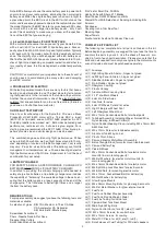
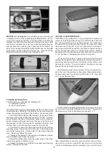
c) If after test flying you find that the ESC or battery are getting
warmer than you would like, make an air exit hole in the bottom
of the fuselage, as shown here. This will improve the air flow
through the fuselage.
❑
36) Mount your propeller on your motor.
The installation of your electric motor system is complete. Skip
ahead to the section on installing the CANOPY.
Skip this section if your using an electric power setup
For this section you will need the Fuselage and:
(2) Nylon Engine Mounts
(4) M4 x 25mm Mounting Bolts
(4) M4 Flat Metal Washers
(1) Fuel Tank
(1) Rubber Stopper Assembly
(1) Fuel Pick-Up Weight (clunk)
(1) Fuel Line Tubing for inside tank
(1) Plywood Fuel Tank Rear Mount
(1) Nylon Throttle Pushrod Tube
(1) 19-1/2" long Wire Pushrod with Z-bend on one end
(1) Metal Pushrod Connector with Set Screw and Hex Nuts
(1) Balsa Block
Note that bolts are not provided for mounting your engine onto the
engine mounts. The bolts provided are for bolting the engine
mounts onto the airplane. Not all engines suitable for the Some-
thin’ Extra use the same diameter mounting bolts. Many will use
6-32 size bolts, while some may use a smaller diameter bolt. It is
up to you to acquire the correct size Bolts(4), Flat Metal Wash-
ers)4), and Lock Nuts(4) to fit your engine. For 6-32 mounting
bolts the correct clearance hole would be a 5/32" dia. drill bit.
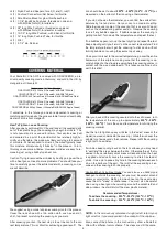
The following instructions show a typical 2-stroke glow engine
being mounted UPRIGHT. We found this to be the most trouble
free installation in the Somethin' Extra.
❑
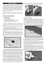
37) Bolt the two Nylon Engine Mounts on the front of the fire-
wall, using M4 x 25mm Bolts and M4 Flat Washers provided.
❑
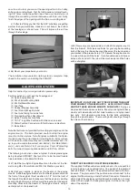
38) Set your engine in place on the beams of the engine
mounts. Slide the engine forward or aft on the engine mounts until
the front of the engine's thrust washer is 4-1/4" from the front of
the firewall. Double check to make sure that the engine is pointing
exactly straight forward, and then mark the locations of the engine
mounting holes onto the beams of the engine mounts, using a
center punch or sharpened nail.
❑
39) Now set your engine aside and unbolt the engine mounts
from the firewall. Drill clearance holes for your engine mounting
bolts all the way thru the engine mount beams at the four locations
you marked in the previous step. TIP: Secure the engine mounts
in a vise while you drill the holes. If at all possible use a drill press
instead of a hand drill - the job will be much easier and the holes
will be straighter.
IMPORTANT: DO NOT USE ANY TYPE OF SCREW TO MOUNT
YOUR ENGINE TO THESE MOUNTS. ALSO, DO NOT DRILL
AND TAP THESE ENGINE MOUNTS FOR BOLTS!
Doing so
may weaken them and cause failure. Mount your engine to these
mounts with steel bolts with flat metal washers and nylon insert
lock nuts. Drill clearance size holes for the bolts completely
through the mount beams. The mounting bolts should go through
the holes without binding.
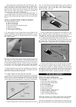
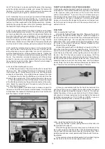
THROTTLE PUSHROD FOR 2-STROKE ENGINES
The supplied throttle pushrod assembly consists of a wire pushrod
running inside a nylon pushrod tube. On one end of the pushrod
wire is a Z-Bend. This end of the pushrod will connect to the throt-
tle servo. The plain end of the pushrod wire will connect to the
engine throttle arm using a metal Pushrod Connector. Determine
which side of the airplane your throttle pushrod will be on. In most
cases with an upright 2-stroke glow engine it will be on the right
side of the airplane.
13
GLOW POWER SYSTEM