


17
Locate the following parts from the kit contents:
q (2) 1/8" dia. x 25-1/2" Nylon Inner Pushrod Tubes
q (4) Metal R/C Links
q (4) M2 Threaded Studs
q (2) Nylon Control Horns
q (4) M2 x 20mm Bolts
❑
1) Mount a nylon control horn on the bottom of the elevator with
two M2 x 20mm bolts and a nylon control horn base. The elevator
control horn goes on the right side of the airplane, the same side
as the elevator servo.
a) Start by holding the control horn in place on the bottom of
the elevator. Make sure it is all the way forward so that the holes
in the arm line up with the hinge line. Use a pencil or pointed tool
to mark the location of the two mounting holes onto the elevator.
b) Drill a 5/64" or 3/32" dia. hole at both of the marks, all the
way through the elevator.
c) Poke two M2 x 20mm bolts through the control horn, and
then through the elevator.
d) As the bolts come through the top of the elevator, engage
the bolt ends into the holes in the nylon control horn base. Tighten
the bolts until the horn and the base are both up against the ele-
vator. Do not over-tighten and crush the wood.
e) Use diagonal cutting pliers to trim-off the excess exposed
ends of the bolts.
❑
2) Mount a nylon control horn on the left side of the rudder with
two M2 x 20mm bolts and a nylon control horn base, using the
same techniques you did in the previous step for the elevator horn.
Make sure to line it up with the rudder pushrod exit hole in the
fuselage side.
❑
3) Assemble and install the ELEVATOR PUSHROD.
a) Install one of the M2 threaded studs into one end of a 25-
1/2” nylon inner pushrod tube. Thread the stud into the tube at
least 1/4”. Thread a metal R/C link onto the stud, centering the
threads to allow equal adjustment in either direction.
b) Slip the opposite end of the pushrod tube into the outer
pushrod sleeve inside the fuselage - on the right side for the ele-
vator servo. Slide it all the way towards the back until you can clip
the R/C link into the outermost hole in the elevator servo arm.
c) Turn on your radio system and check the action of the ele-
vator servo and pushrod up to this point. It should work smooth
and easy. If not, find the source of the trouble and fix it now. It
won't get any better as you go along.
d) Make sure the elevator servo is in neutral position when the
transmitter stick and trim lever are neutral, and then turn the radio
off.
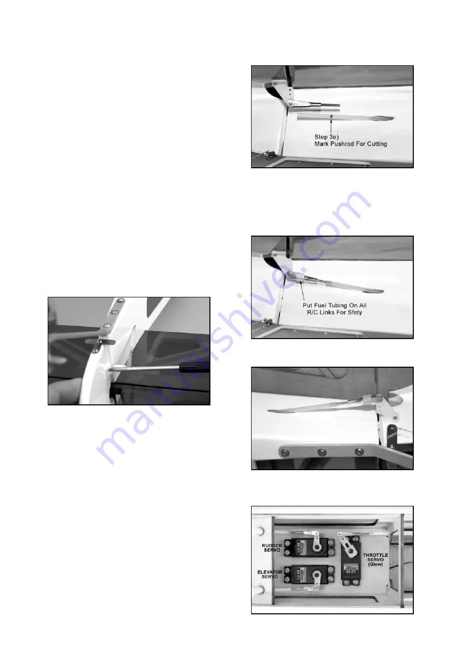
e) At the tail end, clip another M2 threaded stud with R/C link
into the bottom hole of the elevator control horn. Line-up the
threaded stud with the pushrod tube and mark the tube where it
should be cut to accept 1/4” of the exposed threads of the stud.
f) Cut off the inner pushrod tube at the mark made in the pre-
vious step.
g) Screw the threaded stud with R/C link into the end of the
pushrod tube.
h) Turn your radio system back on and check the neutral posi-
tion of the elevator. Adjust one or both of the R/C links as needed
to get it in neutral position.
SAFETY ISSUE: After centering the servo, "safety" each R/C link
by slipping a short length of fuel tubing (not supplied) over the
link, as shown in many of the photos. This will eliminate any
chance of the link opening up in flight and becoming disconnected
from either the control horn or the servo arm. Do this for ALL R/C
links in the airplane!
❑
4) Repeat Step 3 to install the RUDDER PUSHROD.
❑
5) When finished, double check to make sure you have rein-
stalled the screws that hold the servo arms to the servos.