SIG MAYHEM 40 Скачать руководство пользователя страница 13

13

and operate the throttle pushrod tube from the servo end. Make
sure the pushrod can fully open and close the carburetor without
binding.

❑ 

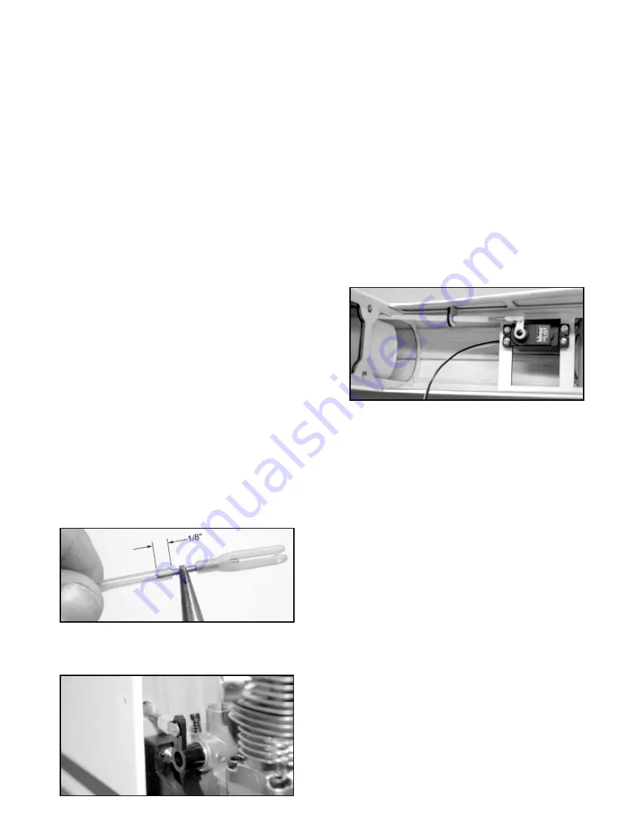
7) Finish the servo end of the throttle pushrod as follows:

a. Turn your radio on and make sure the throttle servo is 

operating in the right direction for high and low throttle. Put the
throttle servo in high throttle position and turn off the radio.

b. Put the throttle pushrod in high throttle position.
c. Inside the fuselage, clip the Threaded Stud with Metal R/C

Link to the servo arm. Hold the threaded stud and the pushrod
tube alongside each other and mark the tube for cutting to length.
Remember to allow for the 1/8" that the threaded stud will be
screwed inside the end of the pushrod tube.

Once you’ve 

determined the correct length, cut off the excess pushrod tube with
a sharp razor knife.

d. Unclip the R/C link from the servo arm and screw the

threaded stud 1/8" inside the end of the pushrod tube, as you did
the other end in step 5. Then reattach the R/C link to the servo
arm. Use a small piece of fuel tubing (not supplied) on the R/C link
to keep it from coming open.

❑ 

8) Turn your radio back on and check the operation of the 

throttle. Adjust the overall length of the throttle pushrod by scewing
the R/C links in or out as needed to achieve full throttle control.
When finished, secure at least one of the R/C links to it's threaded
stud with CA glue, so that the pushrod tube cannot rotate in flight
and change adjustment.

RADIO INSTALLATION, PART IV: Radio System
With all the servos now installed, all that remains is the installation
of the receiver, battery pack and switch.

RX BATTERY PACK: The single heaviest unit of the radio system
is the battery pack. This means that you can, if needed, locate the
battery pack wherever it is needed in the airplane to help achieve
the correct balance point. Be sure to wrap the battery pack in foam
rubber to isolate it from vibration. Use more foam packing, rubber
bands or tie-wraps to secure it to the model structure so that it
can't move around in flight.

RECEIVER:

Wrap the receiver in foam and secure it in the 

fuselage.

Route the receiver antenna outside the model and

secure it back near the tail of the airplane.

Notes about our installation: To achieve proper balance with the
YS-63 in our prototype, we needed to put both the battery pack
and the receiver in the area just in front of the servo tray. So we
wrapped the battery pack and the receiver together in a single
piece of foam rubber, with a seperate piece of foam rubber
between them, as shown in the next photo.

For the receiver antenna, we drilled a 1/16” dia. exit hole in the
right fuselage side at the receiver position. The antenna goes
through the hole and is string back to the tail of the airplane. We

and back into the fuselage. Notice that there is a slot cut in the first
fuselage former behind the firewall for the pushrod sleeve to go
through. This slot keeps the pushrod sleeve out of the area where
the fuel tank is mounted.

❑ 

2) After you get the pushrod sleeve through the slotted former in

the tank area, experiment with different routings of the pushrod
from that point back to the area where the throttle servo will be
located. Once you've decided on the best location for your throttle
servo and route for your pushrod, mount the throttle servo in the
plywood servo tray using the rubber grommets and mounting
screws that came with the servo.

Note: In our installation of the YS-63, we mounted the throttle
servo near the fuselage side (look ahead to next 2 photos to see
our finished throttle pushrod installation). We made a small notch
in the fuselage former that is located at the leading edge of the
wing opening to accomodate the pushrod. It’s a straight shot from
there back to the servo arm.

❑ 

3) Inside the fuselage, slip the Plywood Throttle Pushrod

Support over the end of the pushrod sleeve. The plywood pushrod
support should be positioned near the end of the throttle pushrod
sleeve. Its job is to aim the end of the pushrod directly at the 
throttle servo arm. Feel free to change the overall length of the
pushrod support if necessary to fit your particular installation.
Once you've determined where to mount it, glue the plywood
pushrod support to the fuselage structure.

❑ 

4) Determine how long the pushrod sleeve needs to be to fit your

installation (we purposely provided it too long so it would work with
practically any installation).

In most cases you will need to 

shorten the pushrod sleeve a little bit. As a general rule, the ends
of the pushrod sleeve should be about 1-1/2" away from the servo
arm and the throttle arm. Use a sharp razor blade to cut the
pushrod sleeve to length. Remove the tube and sand its surface
with 220 sandpaper to rough it a little. Reinstall the tube and glue
it in place to the firewall and the plywood pushrod supports.

❑ 

5) Screw the Threaded Stud with R/C Link into one end of the

1/8" od x 12-1/2" Plastic Pushrod Tube. Use a needle nose pliers
to grip the threaded stud so you can screw it in at least 1/8".

❑ 

6) At the firewall, insert the plain end of the plastic pushrod tube

inside the plastic pushrod sleeve. Push it in until the R/C link can
be clipped to engine throttle arm. Then reach inside the fuselage

Содержание MAYHEM 40

Страница 1: ...perly assembled powered and flown the MAYHEM 40 can take you into the exciting world of 3D aerobatic flying Generous wing area lightweight construction and huge control surfaces with large amounts of travel enable the MAYHEM 40 to perform the extreme 3D maneuvers you ve been reading about hovering harriers waterfalls blenders the MAYHEM 40 can do them all NOTE The MAYHEM 40 is not suitable for beg...

Страница 2: ...uel Tank Assembly 1 260cc 8 8 oz Plastic Tank 1 Rubber Stopper 1 Metal Front Clamp 1 Metal Rear Clamp 1 M3 x 19mm PH Clamp Bolt 1 Metal Clunk Pickup 1 Fuel Pickup Tubing for inside tank 1 118 od x 1 9 16 long Aluminum Tube 1 118 od x 2 long Aluminum Tube 1 118 od x 2 3 8 long Aluminum Tube 1 bag 2 1 4 Dia White Spinner Assembly 1 Plastic Spinner Cone 1 Plastic Spinner Backplate 1 Plastic Prop Shaf...

Страница 3: ... it cools Note When trying to remove a warp an extra set of hands are needed Have someone assist you While one person holds the reverse twist in the control surface the other person applies the heat by passing a covering iron over both sides of the part WING ASSEMBLY OVERVIEW The wing of the MAYHEM comes in two pieces a right wing panel and a left wing panel which will be permanently glued togethe...

Страница 4: ...ugh the wing panel until the plug on the end of the wire comes out of the opening in the servo bay Be sure you don t pull all of the Y Harness inside the wing leave the other two plugs of the Y Harness outside at the center of the wing Note You may occasionally feel like the wire has become stuck inside the wing This is simply the plug on the end of the servo wire hitting the side of the holes in ...

Страница 5: ... smears on the plastic covering don t worry about them right now Once the glue is dry you can clean the glue smears off the covering with CA Debonder 5 Allow at least 10 minutes before flexing the aileron After sufficient time has passed flex the aileron up and down several times At first you might notice a little stiffness in the joint This will go away after the hinges have been flexed back and ...

Страница 6: ... step Once you have the horn properly located mark the location of the two control horn mounting holes onto the aileron Drill a 1 16 dia hole completely through the aileron at each mark 3 Mount the control horn in place using the Nylon Retainer Plate on the top side of the aileron and two M2 x 15mm Phillips Head Bolts 4 Repeat the last three steps to mount a control horn on the other aileron 5 Not...

Страница 7: ...g the two 1 4 holes in the plate with the holes in the wing before the glue dries Make sure there is no excess glue inside the holes If necessary run a 1 4 dia drill bit through the holes after the glue is completely dry 5 Now permanently glue the Fuselage Bottom Fairing onto the bottom of the wing with thick CA or epoxy glue Let dry 6 a Bolt the wing back in place on the fuselage Locate the two F...

Страница 8: ...gest using a little thread locking compound Loctite on the mounting bolts to keep them from coming loose Note This kit DOES NOT contain bolts for mounting your engine to the engine mounts That s because not all of the engines that can be used in the Mayhem use the same size bolts Some engines may need 4 40 size bolts while others may need 6 32 You will need to go to the hobby shop to obtain the co...

Страница 9: ... cowl Mount the cowl to the fuselage with the four M2 6 x 8mm PWA Screws provided 4 Determine what size and shape opening you will need in the cowling to accomodate your engine s muffler Then cut the opening in the cowling starting small and gradually opening it up to the final size Note As you can see in the next photo the cutout for the YS 63 muffler in our photo model was a fairly simple 5 8 wi...

Страница 10: ...r is easy to assemble If the diameter of your engine s prop shaft is smaller than the hole in the spinner backplate select a prop shaft adapter to fit If your prop shaft is larger than the hole in the backplate the hole can be drilled larger to fit use drill press Install the backplate and your propeller tightly onto your engine using the engine s prop nut and washer Snap the spinner cone in place...

Страница 11: ... screws that came with the servo 2 Mount a control horn on the BOTTOM OF THE LEFT ELEVATOR Locate the horn at the inboard end of the elevator directly in line with the elevator servo The front edge of the horn s base should be located right at the front edge of the elevator s leading edge bevel Once you have the horn properly located 7 The fin can now be permanently glued in place on the fuselage ...

Страница 12: ...h the engine s carburetor throttle arm From the front insert the 3 16 od x 11 3 8 long Plastic Pushrod Sleeve through the firewall 12 mark the location of the two control horn mounting holes onto the elevator Drill a 1 16 dia hole completely through the elevator at each mark Mount the control horn in place with the Nylon Retainer Plate on the top side of the elevator and two M2 x 15mm Phillips Hea...

Страница 13: ...ce of foam rubber between them as shown in the next photo For the receiver antenna we drilled a 1 16 dia exit hole in the right fuselage side at the receiver position The antenna goes through the hole and is string back to the tail of the airplane We and back into the fuselage Notice that there is a slot cut in the first fuselage former behind the firewall for the pushrod sleeve to go through This...

Страница 14: ...ur MAYHEM with normal control throws before attempting 3D rates FUEL TANK INSTALLATION 1 Assemble the fuel tank as shown We recommend that you plumb your tank with a standard 2 tube setup One of the tubes is the vent line through which you will fuel and defuel the tank The other tube is the fuel feed line to the carburetor Note that the rubber stopper for the tank has two holes that go all the way...

Страница 15: ...a dry cloth Squeegee repeatedly to get as much of the water out from under the decal as possible BALANCE THE MODEL While all airplanes must be balanced to achieve flight the balance of an aerobatic airplane like the MAYHEM 40 is especially critical The final placement of the longitudinal Center of Gravity or Balance Point will have a great effect on the aerobatic performance of this airplane Balan...

Страница 16: ...s you gain confidence Take the MAYHEM to a safe altitude and throttle the engine back to idle This will give you a good idea of the glide characteristics While still at idle steadily increase up elevator to get a feel for the stall characteristics Stalls tend to be very gentle with the nose dropping straight ahead with little tendency to drop a wing This is great information to have when set up fo...

Страница 17: ...e and land the airplane Check all servo mountings and pushrod linkages before flying again If a control surface flutttered once it will flutter again under similar circumstances In general some of the things to look at when trying to cure flutter are Loose servo mounting screws or deteriorated rubber grommets Excessive hinge gap Weak or loose control horn Weak or flexible pushrods Poor fit of R C ...

Страница 18: ...0 to 46 2 Stroke 52 to 70 4 Stroke Wing Span 54 1 2 in 1384 mm Wing Area 746 sq in 48 1 sq dm Length 49 1 2 in 1257 mm Flying Weight 4 5 to 5 lb 2041 to 2268 g Wing Loading 13 9 to 15 4 oz per sq ft Radio 4 channel with 5 servos ...

Отзывы: