background image

.


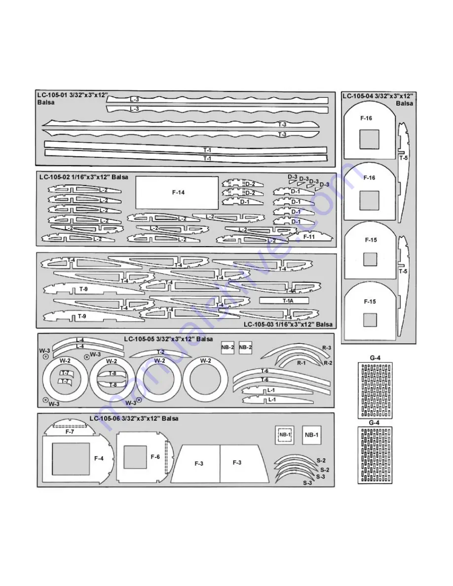
The first thing that you need to do is to identify and mark the part numbers on the laser cut parts using the drawings on the 
following pages as a guide. 
 
It is possible that several of the laser cut parts may not be completely cut through. If this is the case you can free the part from 
the sheet quickly using an X-acto knife. 
NOTE: The slight discoloration on the edges of the laser cut parts may be removed by lightly sanding the edges with 400 grit 
sandpaper.


Содержание Fokker D-VII

Страница 1: ...c Propeller 1 Propeller Shaft 2 Brass Washer 1 Nylon Propeller Bearing 1 1 16 Plastic Tube for Wheel Retainers and Spacers 1 3 16 x60 Rubber Strip 8 Laser Cut Sheets Tools and Building Supplies You will need the following items to assemble this model You must read and follow all of the manufactures instructions provided with these items Glue CA White Glue Sigment or Ambroid all work well Cutting T...

Страница 2: ...llowing pages as a guide It is possible that several of the laser cut parts may not be completely cut through If this is the case you can free the part from the sheet quickly using an X acto knife NOTE The slight discoloration on the edges of the laser cut parts may be removed by lightly sanding the edges with 400 grit sandpaper ...

Страница 3: ...32 sq balsa strip 4 Sand the tail surfaces smooth and round the edges Set the tail surfaces aside until needed later Building the Fuselage 5 Build the fuselage sides over the plan using the laser cut parts F 1 F 2 and F 3 The remaining pieces of the side frames are made from 3 32 sq balsa strip 6 Glue F 4 F 5 and F 6 into position on one of the side frames Use a small square to insure that the for...

Страница 4: ...g board 26 Glue the 3 32 sq leading edge into position 27 Place L 4 into position with the outboard edge raised 3 32 from the building board and glue into position 28 Glue the two 1 16 sq strips into position on the top of the wing 29 Glue the 3 32 sq strips to the L 2 rib at the locations where the N struts will later be attached 30 Remove the wing from the plan and sand the leading edge round ta...

Страница 5: ... building board 51 Glue parts D 1 D 2 a nd D 3 into position 52 Glue the 3 32 sq leading edge into position 53 Glue the three 1 16 sq strips to the top of the ribs 54 Remove from the plan and glue the two 1 16 sq strips into position on the bottom 55 Cut away parts D 2 between the two D 3 s Cover the Model 56 Sand the entire model smooth with 400 grit sandpaper 57 Cover the top forward fuselage wi...

Страница 6: ...into position 78 Make the two N struts from 1 16 x 3 16 spruce 79 Carefully fit and install the N struts to the wings Be careful not to twist the wings while attaching these struts 80 Glue the stabilizer to the fuselage using care to maintain proper alignment 81 Glue the rudder to the fuselage using care to maintain proper alignment 82 Assemble the two machine guns from the parts shown on the plan...

Страница 7: ... damaged buy use or modification In no case shall Herr Engineering Corporation s liability exceed the original cost of the purchased kit Further Herr Engineering Corp reserves the right to change or modify this warranty without notice In that Herr Engineering Corporation has no control over the assembly or use no liability shall be assumed or accepted for any damage resulting from the use by the u...

Отзывы: