background image

AirLink MG90

Hardware User Guide

4118699

Rev 3

Содержание Airlink MG90

Страница 1: ...AirLink MG90 Hardware User Guide 4118699 Rev 3 ...

Страница 2: ... Sierra Wireless modem MUST BE POWERED OFF When operating the Sierra Wireless modem can transmit signals that could interfere with various onboard systems Note Some airlines may permit the use of cellular phones while the aircraft is on the ground and the door is open Sierra Wireless modems may be used at this time The driver or operator of any vehicle should not operate the Sierra Wireless modem ...

Страница 3: ... is a registered trademark of QUALCOMM Incorporated Used under license Other trademarks are the property of their respective owners Contact Information Revision History Sales information and technical support including warranty and returns Web sierrawireless com company contact us Global toll free number 1 877 687 7795 6 00 am to 6 00 pm PST Corporate and product information Web sierrawireless com...

Страница 4: ... 3 1 General Router Specifications on page 30 Added ACMA RCM certification Added Conducted Electrical Transients Corrected RS 232 pin directions in Table 3 2 Serial Connector Pin out on page 33 Added topic GPIO Breakout Cable Revision number Release date Changes ...

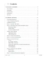
Страница 5: ...0 Chassis 14 Flat Surface Mount 15 Bracket Mount 16 Ground the MG90 Chassis 17 Cabling Best Practices 17 Cable Strain Relief 17 Cable Management 17 Step 3 Connect the Antennas 18 Step 4 Connect the Data Cables 20 Step 5 Connect the Power 20 Fusing 21 DC Voltage Transients 21 MG90 Power Connector 21 Connect the Router to the Vehicle s Electrical System 22 Wiring Diagrams 23 I O Configuration 24 Ste...

Страница 6: ...nducted Tx Power 36 SKU 1102695 1102716 North America Europe 37 SKU 1103007 North America 39 SKU 1103239 1103240 Asia Pacific 41 Carrier Aggregation Combinations 43 Wi Fi Support 44 Mechanical Specifications 45 4 Regulatory Information 46 Important Information for North American Users 46 RF Exposure 46 EU 47 Battery Replacement Disposal 48 A Accessories 49 Antenna Separation 49 GPIO Breakout Cable...

Страница 7: ...cal applications Key Features Multi carrier LTE Advanced WAN connectivity supporting up to 300 Mbps downlink speed Cognitive link management system to optimize WAN connections for quality cost and performance Commercially available to deploy on FirstNet Band14 mission critical networks today Dual concurrent 802 11ac Gigabit Wi Fi 3 x 3 MIMO Precision mobile events reporting at 1 second intervals a...

Страница 8: ...ge 32 9 pin RS 232 Serial Port See Serial Port on page 33 Power Connector See Connect the Power on page 20 Antenna Connectors Reset button See Reboot the MG90 and Reset the MG90 to Factory Default Settings on page 29 GNSS Cellular A Diversity A Wi Fi A Wi Fi WAN 1 2 3 Bluetooth Cellular B Diversity B Wi Fi B Wi Fi Access Point 1 2 3 See Connect the Antennas on page 18 Ground Reprogram Reset Back P...

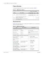
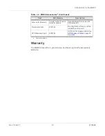
Страница 9: ...sa Part Part Number Description Included with router purchase DC power cable 2000555 10 power cable SMA wrench 5400017 Used to install antenna cables to MG90 Quick Start Guide 5302198 Basic setup and usage instructions Available for separate purchase from Sierra Wireless AC power adapter for test bench use 6001023 Universal adapter Voltage input 100 240 VAC Antenna packages Main Note A secondary a...

Страница 10: ...th Contact Sierra Wireless Sales for options Optional Bluetooth antenna with SMA connector Mounting bracket 6001024 Mounting bracket for easy vehicle installation and removal GPIO Breakout Cable 6001095 RS 232 GPIO breakout cable See GPIO Breakout Cable on page 50 for details a Subject to change Table 1 2 MG90 Accessoriesa Continued Part Part Number Description ...

Страница 11: ... installed and wired into a vehicle s electrical system turn on the ignition If the MG90 is not in a vehicle for example on a test bench use the optional AC power adapter The MG90 should fully power up within two minutes When the MG90 is turning on the Power LED flashes green then turns solid green and other LEDs begin to display their regular behav ior For more information on the LED patterns see...

Страница 12: ...sure to use cables designed and specified for this use to avoid cable failure Installation Overview The steps for a typical installation are performed as follows Step 1 Insert the SIM Cards on page 12 Step 2 Mounting and Grounding the MG90 Chassis on page 14 Step 3 Connect the Antennas on page 18 Step 4 Connect the Data Cables on page 20 Step 5 Connect the Power on page 20 Step 6 Check the router ...

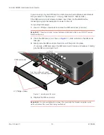
Страница 13: ...tive screws that remain attached to the cover Do NOT remove them from the door 2 Orient the SIM card s as shown in Figure 2 1 Gold contacts on the SIM cards face up 3 Gently slide the SIM cards into their slots until they click into place To remove a SIM card press the SIM card in until it clicks and release it Gently grip the SIM card and pull it out Figure 2 1 Installing the SIM Cards 4 Replace ...

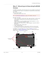
Страница 14: ...to connect all components and perform maintenance Typical locations for installing the MG90 include under the deck lid or on the floorboard of the vehicle s equipment storage Cables will not be constricted close to high amperages or exposed to extreme temperatures The front panel LEDs are easily visible There is adequate airflow It is away from direct exposure to the elements such as sun rain dust...

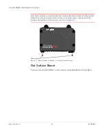
Страница 15: ...ng bracket the MG90 should be positioned with the antenna ports facing down or sideways with the mounting slots resting on mounting posts as shown in Figure 2 3 Figure 2 3 Recommended Orientation for Inclined Vertical Mounting Flat Surface Mount If you are mounting the MG90 on a flat surface use appropriate mounting screws Mounting posts ...

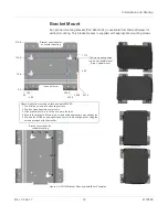
Страница 16: ...l MG90 1 Pre drill two screws into mounting surface 2 Position mounting slots over screws 3 Slide bracket down to lock the screws in the tabs 4 Secure the bracket with two more screws using appropriate mounting holes 5 Position the MG90 as appropriate and secure to mounting bracket using the screws provided with the bracket Bracket orientation for horizontal mounting Bracket orientation for vertic...

Страница 17: ...ntenna data and power cables from other wiring in the vehicle and route away from sharp edges Cable Strain Relief Sierra Wireless recommends using cable strain relief for installations in high vibration environments Place the cable strain relief within 200 mm 8 of the MG90 to reduce the mass of cable supported by the power connector under vibration Ideally the strain relief mounting for the DC cab...

Страница 18: ...re 2 6 Antenna Connectors Rear Panel GNSS Cellular A Diversity A Wi Fi A Wi Fi WAN Bluetooth Cellular B Diversity B Wi Fi B Wi Fi Access Point First Radio Second Radio if installed 1 2 3 1 2 3 Table 2 1 Antenna Connector Types Module Connectors Description Type Radio Cellular A First radio Rx Tx SMA Diversity A First radio Rx Diversity SMA Radio Cellular B Second radio Rx Tx SMA Diversity B Second...

Страница 19: ...P SMA connectors on the MG90 s rear panel From left to right as shown in Figure 2 6 on page 18 If used connect the GNSS antenna to the GNSS antenna connector For the first radio module Connect the main antenna to the Cellular A connector If used connect the diversity antenna to the Diversity A connector Connect the Wi Fi Access Point module s three antennas to the Wi Fi A connectors If used connec...

Страница 20: ...irements Figure 2 8 Data Cable Connectors Rear Panel Step 5 Connect the Power The router s power supply cable must be connected to the vehicle s fuse box and installed along the vehicle wall always inside the vehicle cabin and must not cross the vehicle s firewall protection Always follow the vehicle manufacturer s recommendations for electrical accessories connections All components used in the e...

Страница 21: ... Sierra Wireless recommends fusing the power input using a 9 A fast blow fuse recommended to have no more than 10 de rating over the operating temperature range DC Voltage Transients The MG90 has built in protection against vehicle transients including engine cranking down to 5 0V and load dump so external power conditioning circuits are not needed For details see Industry Certification for Vehicl...

Страница 22: ...able to the MG90 9 Reconnect the vehicle s battery a Connect the positive terminal first b Connect the negative terminal Table 2 2 Power Connector Pin and DC Cable Wires Pin Name Associated DC Cable Wire Color Description Type 1 Power Red Note If you want to turn the MG90 on off using a control line such as a vehicle ignition line Sierra Wireless strongly recommends that you connect the control ig...

Страница 23: ...rce Include a 9 A fast blow fuse recommended to have no more than 10 de rating over the operating temperature range in the input power line Sierra Wireless recommends using a continuous unswitched DC power source Connect the power through the vehicle s fuse box Pin 2 Ground Use the black wire in the DC cable to connect Pin 2 to the vehicle battery s negative terminal or ground See also Step 2 Moun...

Страница 24: ...act switch inputs See Figure 2 13 on page 25 Digital Input You can connect any of the GPIO pins to a digital input to detect the state of a switch or to monitor an external device such as a motion detector a remote solar panel or a remote camera Digital input can also be used with the standby timer While in Standby mode the digital input will not be acted upon if it changes state Figure 2 12 Digit...

Страница 25: ...r cord with the corresponding slot on the power socket and fully insert the connector The lock snaps into place when the cord is correctly inserted This protects the power cord against accidental discon nection caused by vehicle vibrations Table 2 3 Digital Inputa a Voltage levels are compatible with 3 3V TTL standard logic families Pull up State Minimum Typical Maximum Units Off Low 0 7 V High 2 ...

Страница 26: ...ode is enabled by default so in order to avoid the router powering on in standby mode ensure that it is supplied with more than 11 V at startup Ignition Sense pin 3 is connected to the battery or power source see Step 5 Connect the Power on page 20 for details LED Behavior Figure 2 15 MG90 LED Status Indicators front panel Locking connector GNSS Wi Fi Network Signal Activity Power Table 2 5 LED Be...

Страница 27: ...dio Solid Green Good signal 85 dBm equivalent to 4 5 bars Solid Amber Average signal 100 dBm 85 dB equivalent to 2 3 bars Red Poor signal 100 dBm equivalent to 1 bar Activity Flashing Green Transmitting receiving over the WAN interface Off No WAN activity Power Solid Green Power is present normal operation Flashing Green Power is present MG90 is booting Solid Amber Standby mode Flashing Red Slow b...

Страница 28: ...ub tabs To access the LCI 1 Connect a laptop to the router with an Ethernet cable use any of the Ethernet ports 1 4 By default ports 1 4 are configured as LAN connections and port 5 is configured as a WAN connection 2 Launch your web browser and go to 172 22 0 1 MG LCI Note that the URL is case sensitive Figure 2 16 LCI Login Screen 3 Enter the default User name and Password and click Login User N...

Страница 29: ... the factory default settings 1 On the front of the unit press the Reset button for the Button Reset Time configured in the LCI s General Shutdown tab factory default is 10 seconds 2 When all the LEDs turn solid white release the Reset button When the factory reset is complete the MG90 powers off and if AutoPower is enabled LCI General Startup tab will reboot Boot the MG90 from USB for Software Up...

Страница 30: ...missions Immunity CE Including EMC Test case for vehicle installation EN301489 ACMA RCM FCC Industry Canada Safety CB Scheme UL 60950 Industry Certification for Vehicles E Mark 72 245 EEC 2009 19 EC ISO7637 2 SAE J1455 Shock Vibration Environmental Compliance RoHS 2011 65 EU RoHS 2 WEEE GSM UMTS Certifications PTCRB GCF CC R TTE Reliability MTBF Ground Benign 25 C 203 409 hours 23 22 years MTBF ca...

Страница 31: ... condensing Ingress Protection IP rating IP64 if RJ45 and USB connectors are covered Drop non operational ISTA 2A 2001 test categories 1 4 5 and 6 Mobile Network Operator Certification Verizon Wireless AT T Other major network operators pending Network Technology LTE DC HSPA For SKU specific lists of supported bands see Radio Bands Conducted Tx Power on page 36 Host Interfaces Antenna connectors S...

Страница 32: ...unctional but is unable to be upgraded OTA Over The Air The MG90 Software Configuration User Guide contains the details of USB mode configuration and driver installation Ethernet 5 Gigabit 10 100 1000 Base T RJ45 Ethernet ports IEEE 802 3 Ethernet specification for 1000 Mbps speed Gigabit Ethernet with fallback to 100 or 10 Mbps Cat 5e or Cat 6 cable is required for Gigabit Ethernet Auto crossover...

Страница 33: ...r Note An RS 232 GPIO Breakout Cable is available See GPIO Breakout Cable on page 50 for details SIM Card Interface Four mini SIM 2FF slots Two for each installed radio module 1 8 V 3 3 V This interface is compliant with the applicable 3GPP standards for USIM Table 3 1 General Router Specifications Continued 1 2 3 4 5 6 7 8 9 Table 3 2 Serial Connector Pin out Name Pin Description Type DCD 1 GPIO4...

Страница 34: ... Depth 8 7 in 22 0 cm Height 2 4 in 6 0 cm Housing The MG90 is made of ruggedized powder coated aluminum RoHS The MG90 complies with the Restriction of Hazardous Substances Directive RoHS This directive restricts the use of six hazardous materials in the manufacture of various types of electronic and electrical equipment Screw Torque Settings Mount screws M6 40 kgf cm 3 92 Nm 35 in lb Screws are i...

Страница 35: ... IP DNS IPv4 Routing NAT Host Port Routing DHCP VLAN GPS NMEA TAIP Vehicle Area Networking LAN Support for all on board devices wired and wireless IEEE 802 11 b g n ac built in vehicle AP 10 100 1000 Base T Ethernet RJ45 x 5 ports Bluetooth Serial RS 232 DB 9 DHCP Server RFC 2131 USB USB 3 0 x 2 Type A female Compatibility Operates with Wi Fi certified client devices Supports all major client oper...

Страница 36: ...OBIKE Authentication and Accounting 802 1x RADIUS authentication Management Manage mobile network vehicle and network health when operated with AMM Management Operational support services for fault configuration accounting performance and security Network coverage reporting Location based reporting Historical logging Remote software updates Secure VNC reach through Email alerts for configurable th...

Страница 37: ... 1785 MHz 1805 1880 MHz Band 4 1710 1755 MHz 2110 2155 MHz Band 5 824 849 MHz 869 894 MHz Band 7 2500 2570 MHz 2620 2690 MHz Band 8 880 915 MHz 925 960 MHz Band 12 699 716 MHz 729 746 MHz Band 13 777 787 MHz 746 756 MHz Band 20 832 862 MHz 791 821 MHz Band 25 1850 1915 MHz 1930 1995 MHz Band 26 814 849 MHz 859 894 MHz Band 29 n a 717 728 MHz Band 30 2305 2315 MHz 2350 2360 MHz Band 41 2496 2690 MH...

Страница 38: ... 30 41 22 1 UMTS Band 1 IMT 2100 12 2 kbps Band 2 UMTS 1900 12 2 kbps Band 3 UMTS 1800 12 2 kbps Band 4 AWS 1700 2100 12 2 kbps Band 5 UMTS 850 12 2 kbps Band 8 UMTS 900 12 2 kbps 23 1 Connectorized Class 3 Table 3 6 GNSS Bands Supported SKU 1102695 1102716 Band Frequency GPS 1575 42 MHz GLONASS 1602 MHz COMPASS BeiDou 2 1561 098 MHz Galileo Future software support QZSS ...

Страница 39: ...0 1755 MHz 2110 2155 MHz Band 5 824 849 MHz 869 894 MHz Band 7 2500 2570 MHz 2620 2690 MHz Band 8 880 915 MHz 925 960 MHz Band 12 699 716 MHz 729 746 MHz Band 13 777 787 MHz 746 756 MHz Band 14 788 798 MHz 758 768 MHz Band 20 832 862 MHz 791 821 MHz Band 25 1850 1915 MHz 1930 1995 MHz Band 26 814 849 MHz 859 894 MHz Band 29 n a 717 728 MHz Band 30 2305 2315 MHz 2350 2360 MHz Band 41 2496 2690 MHz ...

Страница 40: ... 41 22 1 Band 14 23 2 UMTS Band 1 IMT 2100 12 2 kbps Band 2 UMTS 1900 12 2 kbps Band 3 UMTS 1800 12 2 kbps Band 4 AWS 1700 2100 12 2 kbps Band 5 UMTS 850 12 2 kbps Band 8 UMTS 900 12 2 kbps 23 1 Connectorized Class 3 Table 3 9 GNSS Bands Supported SKU 1103007 Band Frequency GPS 1575 42 MHz GLONASS 1602 MHz COMPASS BeiDou 2 1561 098 MHz Galileo Future software support QZSS ...

Страница 41: ...Hz 2620 2690 MHz Band 8 880 915 MHz 925 960 MHz Band 18 815 830 MHz 860 875 MHz Band 19 830 845 MHz 875 890 MHz Band 21 1447 9 1462 9 MHz 1495 9 1510 9 MHz Band 28 703 748 MHz 758 803 MHz Band 38 2570 2620 MHz TDD Band 39 1880 1920 MHz TDD Band 40 2300 2400 MHz TDD Band 41 2496 2690 MHz TDD WCDMA Band 1 1920 1980 MHz 2110 2170 MHz Band 5 824 849 MHz 869 894 MHz Band 6 830 840 MHz 875 885 MHz Band ...

Страница 42: ...UMTS 1700 12 2 kbps Band 19 AWS 850 12 2 kbps 23 1 Connectorized Class 3 TD SCDMA Band 39 23 1 Table 3 12 GNSS Bands Supported SKU 1103239 11032400 Band Frequency GPS 1575 42 MHz GLONASS 1602 MHz COMPASS BeiDou 2 1561 098 MHz Galileo Future software support QZSS Table 3 11 Conducted Tx Power SKU 1103239 1103240 Continued Band Conducted Tx Power dBm Notes ...

Страница 43: ...carrier aggregation combinations Table 3 13 Supported LTE Carrier Aggregation Combinations SKU 1102695 1102716 1103007 1 8 2 2 5 12 13 29 3 7 20 4 4 5 12 13 29 5 2 4 30 7 3 7 20 8 1 12 2 4 30 13 2 4 20 3 7 30 5 12 41 41 Table 3 14 Supported LTE Carrier Aggregation Combinations SKU 1103239 1103240 1 8 18 19 21 3 5 7 19 28 5 3 7 7 3 5 7 28 8 1 18 1 19 1 3 21 21 1 19 28 3 7 38 38 39 39 40 40 41 41 ...

Страница 44: ...t where it can connect to the local access point 802 11 b g n ac Wi Fi B Default configuration Wi Fi Access Point The VAN supports connections to the router by wired devices over Ethernet ports and wireless devices 802 11 b g n ac Throughput LTE Advanced 300 Mbps WPA2 Enterprise RSA with AES encryption 4 SSIDs with separately configurable security bandwidth and QOS Up to 64 clients can connect sim...

Страница 45: ... 3 Feb 17 45 4118699 Mechanical Specifications Figure 3 3 MG90 Mechanical Specifications Top view Back view Front view Side view 5 3 lb 2 4 kg Weight Mounting holes LEDs G N S S W i F i N e t w o r k S i g n a l A c t i v i t y P o w e r ...

Страница 46: ... try to correct the interference by one or more of the following measures Reorient or relocate the receiving antenna Increase the separation between the equipment and receiver Connect the equipment into an outlet on a circuit different from that to which the receiver is connected Consult the dealer or an experienced radio TV technician for help Warning Changes or modifications to this device not e...

Страница 47: ...ements and other relevant provisions of Directive 1999 5 EC The MG90 displays the CE mark Warning Changes or modifications to this device not expressly approved by Sierra Wireless could void the user s authority to operate this equipment Warning This product is only to be installed by qualified personnel Device FCC ID IC Number Technology Band Maximum Antenna Gain dBi MG90 N7NMC7455 2417C MC7455 L...

Страница 48: ... supplier at the end of its life WEEE products may be recognized by their wheeled bin label on the product label Battery Replacement Disposal The MG90 uses a BR2032 coin type lithium battery to power its RTC Real Time Clock For an installed MG90 the battery should meet or exceed the operational lifetime of the unit For a device in storage the battery will last up to 5 years Caution Risk of explosi...

Страница 49: ...le A 1 Recommended Antenna Separation Antenna Separation Service Frequency MHz Wavelength mm Best 1 2 mm Good 1 4 mm LTE 700 428 214 107 800 375 187 94 850 353 176 88 900 333 167 83 1700 176 88 44 1800 167 83 42 1900 158 79 39 2100 143 71 36 2300 130 65 32 2500 120 60 30 2600 115 58 29 WCDMA 850 353 176 88 900 333 167 83 1700 176 88 44 1800 167 83 42 1900 158 79 39 2100 143 71 36 ...

Страница 50: ...t Release Date 2017 Length 113 8 117 7 in 2890 2990 mm Table A 3 Pin Assignments Pin Color Interface Function Direction 1 Black GPIO GPIO4 Input Outputa a GPIO pins are digital input only Digital output to be supported by future software update 2 Grey Serial Rx Input 3 Yellow Serial Tx Output 4 Purple GPIO GPIO2 Input Outputa 5 Orange Serial GND Ground 6 Red GPIO GPIO3 Input Outputa 7 Brown Serial...

Отзывы: