


User Guide v.1.0 Siensor UNIC
5. Connecting the LLS to a PC via Siensor UNIC
To connect the LLS to a PC using
Siensor UNIC,
do the following:
1.
Make sure that the
Siensor UNIC
current operating mode corresponds to the interface used by the con-
nected LLS, i.e. the RS-232/RS-485 mode switch (see Fig. 3.1) is in the required position. For example, the
Siensor AF107 LLS uses the RS-485 interface for configuration and therefore the mode switch of
Siensor
UNIC
must be in the RS-485 position. The Siensor D107 LLS can use both RS-232 and RS-485 for configu-
ration and further operation, thus the mode switch position is irrelevant for configuration of this type of sen-
sors.
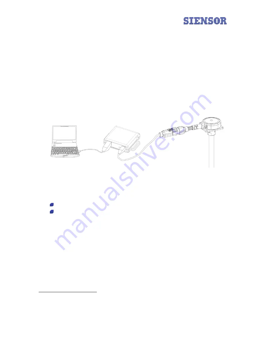
2.
Connect
Siensor UNIC
to a free USB port of a PC using the cable coming with the device package (see
Fig. 5.1). The red LED must light up on the top of the
Siensor UNIC
housing (power indicator).
Fig. 5.1
Connecting Siensor UNIC to a PC USB port
3.
Connect the LLS to
Siensor UNIC
using the corresponding cable adapter
∗
(see Fig. 5.1).
4.
Run the
Siensor Monitor
application on a PC (or similar software, if a sensor from other manufacturer is
connected via
Siensor UNIC
).
SiensorMonitorDP – software for configuration of the Siensor D107 sensors;
SiensorMonitorAP – software for configuration of the Siensor AF107 sensors.
5.
Click
Settings
in the application toolbar (top left corner of the window) (see Fig. 5.2).
∗
Cable adapters for other LLS are supplied separately
11


