Mobility, Intelligent Traffic Systems
Sopers Lane, Poole, Dorset, BH17 7ER
Security
classification Unrestricted
Page
74 of 92
Version
3
Status
Issued
Last Editor
Alan Doyle
Date
05-Oct-2017
Document Name
Stratos Outstation General and ICM Handbook Document No. 667/HB/52250/000
Copyright © Siemens plc 2014. All Rights Reserved. Mobility and Logistics is a division of Siemens Plc
7.3.1 Replacing the CPU Board
1. If any I/O boards are fitted these will need to be removed to gain access to the
CPU board. Refer to later in this section for removal procedure.
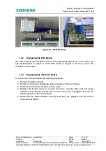
2. Unscrew the four short pillars (or long + short mounting pillars if an I/O board was
fitted) shown in Figure 20 below.
3. Lift the
back
of the board clear of the rear mounting studs and slide the board back
to clear the front connectors from the front panel then lift the board vertically off the
front studs as shown in Figure 21 below.
4. Be careful not to invert the unit as the four loose spacers that were under the CPU
board will slide off.
5. To fit the new board, place the mounting front slots over the front pillars with the
rear of the board raised above the rear mounting pillars.
6. Slide the board forward to engage the connectors into the front panel holes and
then drop the rear of the board onto the rear mounting pillars.
7. Refit the four short pillars.
8. Refit the four long pillars if an I/O board is fitted.
9. Refit the I/O board(s) if applicable following the I/O board replacement procedure
below.
10. Transfer the Heart (SD card) and License card from the old CPU board to the new
CPU board with reference to sections 4.4.2 and 4.4.3.
Figure 20 – CPU Board Fixings


