


Siemens Building Technologies
CM1N4573E / 06.2001
Landis & Staefa Division
3/8
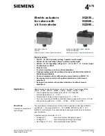
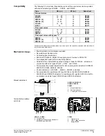
The following 5.5 mm stroke, threaded two-port and three-port valves can be operated
with electric actuator types SQS35... , SQS65... and SQS85...
Type
DN [mm]
PN [bar]
Data sheet
Two-port valves
VVG44...
15 ... 40
16
N4364
VVP45...
10 ... 20
16
N4845
VMP43...(2)
15, 20
16
N4841
VMP44...(2)
15, 20
16
N4844
VVG55...
15 ... 25
25
N4379
VVI52...
15
25
N4377
Three-port valves
VXG44...
15 ... 40
16
N4464
VXP45...
10 ... 20
16
N4845
VMP43...
15, 20
16
N4841
Three-port valves with bypass "T"
VMP45...
10 ... 20
16
N4845
VMP43...(4)
15, 20
16
N4841
VMP44...(4)
15, 20
16
N4844
The admissible differential pressure values
∆
p
max
and
∆
p
s
for the complete motorised valve are shown in
the relevant valve data sheets.
•
Electric actuator, no maintenance required
•
Reversible synchronous motor
•
Anti-locking gear mechanism
•
SQS35.50, SQS35.53, SQS65.5 have spring return function to DIN 32730
•
Load-dependent switch-off in stroke limit positions
•
Selectable flow characteristic:equal percentage or linear for SQS65… actuators in
conjunction with valve types VVG44..., VVI52... and VXG44...
•
Directly impacting manual adjustment for all non-spring-return actuators: SQS35.00,
SQS35.03, SQS65, SQS65.2, SQS85...
•
Position indicator on all SQS35..., SQS65..., SQS85... actuators
•
Accommodation for auxiliary switch type ASC9.6 on the SQS35.00, SQS35.03,
SQS85.00 and SQS85.03 actuators. An auxiliary switch (
not the ASC9.6) is built in
as standard in actuator types SQS35.50 and SQS35.53 actuators.
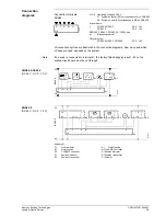
3
1
2
4573Z03
SQS35.00, SQS35.03
SQS65, SQS65.2
SQS85...
1
Manual adjustment
2
Position indication
3
Coupling bolt for valve neck
6 7 5
01163
UM
RY
G
G
0
R - M
A C B
S1
6 7 5
01163
UM
RY
G
G
0
R - M
A C B
S1
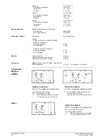
SQS35..., SQS85...
5
Terminal strip
6
Auxiliary switch built-in as standard in
SQS35.50 and SQS35.53
SQS65...
5
Terminal strip
6
«lin» / «log» connection
7
Bridge R
−−−−
M
Compatibility
Mechanical design
Manual adjustment
Terminal strip, auxiliary
switch etc.